Dielectric heating is a high frequency alternating electric field or radio-frequency or microwave electromagnetic radiation heating caused by dielectric loss. The process of dielectric heating can be used to heat non-metallic materials that do not conduct electricity. By this method, uniform heating of non-conducting material can be achieved. The process of dielectric heating is also called high frequency or capacitive heating.
Principle of Dielectric Heating :
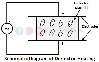
The principle of dielectric heating is based on dielectric loss. A dielectric material is basically a poor conductor or insulator such as wood, plastic, glass, ceramics, etc. We know that each and every material is made up of molecules whose elemental particle is an atom. When the dielectric material is not present in the electric field, the polar molecules in the material are randomly arranged as shown below.
When these molecules are subjected to the influence of the alternating electric field, the molecules in the material undergo polarization. Due to the formation of dipoles on polar molecules, the dipole moments of the polar molecules get properly oriented as shown above.
The orientation of the polar molecules will be according to the direction of the impressed alternating electric field. Since the electric field applied is alternating, the orientation of the polar molecules will be changed for every half cycle of the supply. The speed at which the orientation of the polar molecules changes will depend upon the frequency of the supply.
In doing so, atoms in the material get stressed due to inner atomic friction for which some energy will be wasted as the dielectric loss. This dielectric loss in dielectric material when subjected to an alternating electric field will results in the production of heat thereby increasing the temperature of the material.
The increase in temperature is due to the dielectric loss which is converted into heat. This loss is due to the reversal of magnetism or magneto molecular friction and is similar to hysteresis loss in ferromagnetic material.
Circuit Diagram and Working of Dielectric Heating :
The below figure shows the schematic arrangement of dielectric heating. It consists of two electrodes or metal plates in between a dielectric material that is to be heated is placed. An ac supply of high frequency is applied across the two electrodes.
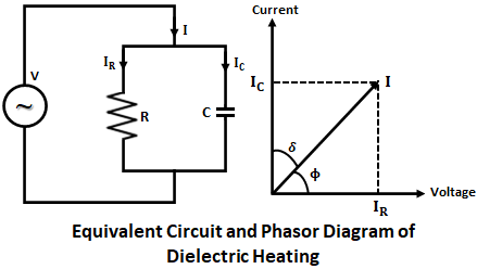
Since there is no perfect conductor and insulator, the above capacitor when connected to the supply. The current drawn will never lead the voltage exactly by 90°. Due to the presence of some resistance in the capacitor, there exists some in-phase relationship between the voltage and current.
This causes some power loss in the dielectric material between the electrodes, thereby producing heat in the dielectric material as a dielectric loss. In order to obtain sufficient heating of the material i.e., to obtain required dielectric loss in the material, the frequency of the supply should be very large.
The below shows the equivalent circuit and phasor diagram for the above shown schematic arrangement of dielectric heating. The current consists of two components IC and IR, where IC is the capacitive current leading the voltage by 90° and IR is the in-phase current with voltage due to resistance.
Let,- V = Supply voltage,
- f = Supply frequency in Hz,
- A = Area of electrode or plate,
- t = Thickness of dielectric,
- δ = Loss angle in radian,
- C = capacitance of condenser.
Therefore dielectric loss is given by,
For any material, C and δ are constant. Thus, the heat produced is proportional to V2 and f. Therefore, for obtaining adequate heating, a voltage in the range of 15-20kV and a frequency of about 10-40MHz are usually employed. But, there are various factors that decide the frequency and voltage of dielectric heating.


