The current collecting system is a fundamental part of electric traction by which the electrical power is supplied to the traction motor. The electrical power from the fixed power installation is transferred to the running vehicle by providing appropriate sliding contact with the stationary conductor.
Typically the system consists of one or more spring-loaded arms with sliding shoes mounted on the vehicle. The spring force presses the contact shoe onto the stationary conductor to maintain contact with it. As the vehicle moves, the contact shoe slides along the stationary conductor to draw the electrical power to run the traction motor. The following are the different types of current collecting systems used in electric traction.
Conductor Rail Collector :
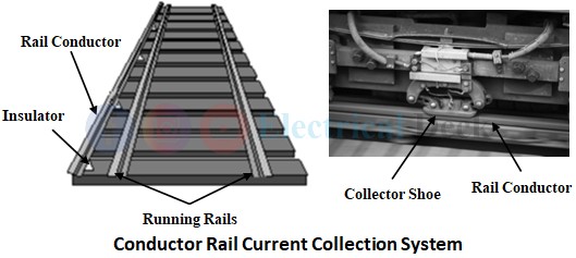
In earlier days, the conductor rail collector is the most used current collecting system in many countries for electric traction. As the name implies, rail conductors are used in this system that supplies electric power to the locomotive. The rail conductor is placed parallel to the rail track and runs along the rail track.
There can be one or two rail conductors running along the track. In the case of one rail conductor, the rail track acts as the return path. The rail conductors are mounted on the insulators placed parallel to the track at a distance of 0.3 to 0.4m from the track. The upper surface of the rail conductor will be in contact with the running rail and is connected to the substations at suitable points.
The locomotive is equipped with collector shoes that maintain contact with the rail conductor and collect current from it as shown above. This type of system has capable of collecting heavy currents. The collector shoe can be either top contact or side contact type. For voltages up to 700V top contact-type shoe is used, and for voltages up to 1200V, side contact-type shoe is used.
While designing the rail conductor, its electrical properties are mostly considered rather than mechanical properties. Because during starting time period, the motor will draw huge current which results in wearing of the rail conductor due to traction of locomotive collector shoe.
The characteristics that are to be considered while designing rail conductors are cost, wearing qualities, shape, and size of the conductor, electrical conductivity, and amount of contact surface available for the collector shoe. The main advantages of this current collection system are it is cheap and easy to repair and inspect. The disadvantages of this system are the insulation of the conductor becomes difficult at high voltages and endangers the safety of the personnel.
Trolley Collector :
This type of current collector is used in tramways and trolleybuses. It consists of a grooved wheel or sliding shoe attached to one end of a trolley pole mounted on the roof of the vehicle. The wheel or shoe will maintain contact with the overhead conductor wire and supplies power to the motor as shown below.
The main drawback of this type of collector is that, if suppose the vehicle is operated in the reverse direction, the collector has to be rotated through 180°. This type of collector is suited for electric traction systems running at low speeds (20-30kmph).
Bow Collector :
Bow collector is used in tramways for current collection from overhead distribution conductor. It consists of two bow poles, at the end of these poles a light metal strip up to 1m length is attached that collects current from the overhead conductor as shown below.
Though the bow collector has smaller inertia, it cannot be used for collecting large currents. The traction system with this type of current collector can run at high speeds without leaving the contact wire. Materials such as copper, aluminum, or carbon are used for the current collection strip.
Similar to the trolley collector, when the vehicle needs to be operated in the reverse direction, the bow collector has to be reversed or there should be a provision for another bow collector mounted in the reverse direction.
Pantograph Collector :
The disadvantages of a bow collector can be overcome by using a pantograph collector. Pantograph is used for collecting currents in the range of 2000A to 3000A at operating speeds of 100kmph to 130kmph even during extreme climatic conditions. Similar to bow collectors, pantograph collectors are mounted on the roof of the locomotive which carries a strip about 1.2m long that maintains contact with the overhead conductor.
There may be a single or two strips on each pantograph. The strip may be straight or in the form of an auxiliary bow. The material used for the pantograph is steel with plates of copper or bronze inserted. This arrangement is supported with the help of springs on a framework of pentagonal shape.
The pantograph must have continuous contact with overhead wire at constant pressure. It must be light and follow the changes in height of the contact wire. It should have minimum inertia even at high speeds. There are two types of pantograph collectors. They are,
- Diamond pantograph.
- Faiveley pantograph.
Diamond Pantograph :
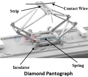
The initial design of the pantograph was symmetrical and diamond-shaped as shown below. It consists of a steel channel section fitted with renewable collector strips and supported on the top of the tubular framework. Strips slide along the contact wire as the train moves. The contact pressure is such that there will be minimal wear on the contact wire.
In the case of a dc system, the current collection is done through metal collector strips such as copper, copper steel combination, manganese steel, aluminum, or bronze. This needs lubricating medium such as grease containing graphite etc.
This can be overcome by using metalized carbon strips. In the case of a 25kV ac system, since the current to be collected is small, a single pantograph is sufficient. For a 1500V dc system, the current will be in the order of 2500A, so two pantographs are needed.
The tensioning springs mounted on the base of the pantograph will rotate the horizontal shafts which are attached to all the four lower arms of the frame in such a way that all of them rise and fall together. The drawback of a diamond pantograph is that it requires a lot of roof area. The advantages of a diamond pantograph collector are,
- It can operate in either direction of motion.
- The erection is simple.
- The risk of jumping off the collector is minimum.
- Its height can be easily increased or decreased.
Faiveley Pantograph :
In the case of 25kV ac, the contact wire of overhead equipment is light in weight. So low contact pressure (6.5 kg to 9 kg) as against high pressure (10 kg to 15 kg) in dc pantograph. So, a lightweight single-ended Faiveley pantograph can be used for ac traction. To ensure light construction with low inertial forces, the latest designs developed by Faiveley have fewer arms and are asymmetrical.
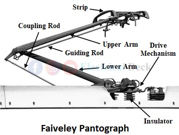
Faiveley pantograph consists of base, articulated system, pneumatic control system including throttle valve, two raising springs, and four insulators as shown in the below figure. The articulated system is placed on the base made up of welded sections. The articulated system consists of the following parts.
- Horizontal spindle turning into two ball bearings which are part of the base.
- Lower arm with horizontal spindle and support at the upper end bearing on which is carried the articulated system.
- The guiding rod ensures the positioning of the upper arm as the lower arm rotates.
- Transversal tubes are connected to the pan positioning rod and spring boxes.
When compressed air is allowed into the control cylinder, the air pressure cause to compress of the holding down springs through the piston which in turn permits the horizontal spindle to rotate under the action of up springs. Then partograph rises until it touches the overhead conductor. Then after the articulated system stops and the piston completes its stroke. From now onwards, the air motor stops working and the piston remains stationary.
When the control cylinder is opened, the holding spring force makes the piston return its position. Slotted rod presses on the pin of the horizontal spindle lowering the articulated system. The pantograph can be raised or lowered from the driver's cabin in the following methods,
- Air raised gravity lowered.
- Air raised spring lowered.
- Spring raised air lowered.
In air-raised pantographs, failure of air pressure would make locomotive inoperative. If air leaks, contact pressure also reduces and the effective current collection is not possible. A catch is employed to prevent bouncing of the pantograph and it needs constant pressure to keep it in a lowered position in case of air lowered pantograph.


