The distance protection scheme is widely employed for the protection of very long high voltage transmissions lines and sub-transmission lines which provide discrimination protection without employing pilot wires. A distance relay operates by sensing the impedance to fault i.e., the working of a distance relay is based on the measurement of the impedance of the line between the location of the relay and the fault point.
The factors to be considered while selecting a distance protection scheme are system configuration, number of stations in series, the distance between each point, other protection which will exist in line, the necessity of high-speed auto reclosures, and the necessity of directional features.
Protection of Transmission Line Using Distance Relay :
The distance relay measures the ratio V/I at the relay location which gives the measure of distance between the relay and fault location. The impedance (resistance/reactance/admittance) of a fault loop is proportional to the distance between the relay location and the fault point.
If the ratio V/I is less than Z (the impedance of the line section being protected) the relay will trip instantly. If V/I is greater than Z, it indicates that the fault is beyond the protected line and the relay will not trip. There are two types of distance relays,
- Definite distance relay, and
- Time distance relay.
Definite Distance Relay :
The application of distance relays for the protection of transmission lines is shown in the below figure. G is generating station, substations S1, S2, and S3 are in series. Let the impedance of line GS1 be Z1. S1S2 be Z2, S2S3 be Z3. The relays at G, S1, S2, and S3 are set to operate for impedance less than Z1, Z2, Z3, and Z4 respectively.
Suppose a fault takes place at point P between substations S2 and S3. The total fault loop impedance from generating station up to fault point is Z1 + Z2 + Z, from substation S1 to fault is Z2 + Z, and from substation S2 to fault is Z.
Therefore the relays at generating station and substation S1 will not operate, but the fault loop impedance for the relay at substation S2 becomes less than Z3 (because Z is less than Z3), therefore, the relay at substation S2 will operate. Similarly, in case of a fault occurring between S1 and S2, the relay at S1 will operate. Thus, in this way, instantaneous protection can be achieved for all conditions of operation.
Time Distance Relay :
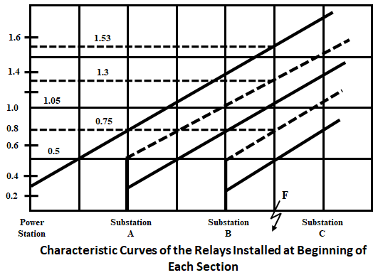
The below shows a simple power system with a time distance relay at the power station and substations A, B, and C.
The below figure illustrates the characteristics curves of the relays installed at the beginning of each section. Let there be a fault in between substations B and C at point F. The time distance relay at substation B will trip in 0.5 sec. While the relay at sub-section A and at the power station will operate in 1.05 and 1.53 sec respectively.
In order that the fault may be cleared by the nearest circuit breaker first the circuit breaker operation time should also be included, and if the current breaker opening time is assumed to be 0.25 sec after its trip contacts energize, the breaker operation time is modified to be represented by dotted lines for substations A and B.
Further, it will be obvious that the distance relays at substation A and at the power station will act as backup relays for fault at point F, i.e., if the relay at station B fails to operate, the relay of substation A will trip the circuit after 1.3 sec (including time of CB operation) and even relay at substation A fails to operate, then the relay at the power station will trip the circuit in 1.53 sec.
Combined Protection Using Definite Distance and Time Distance Relay :
When the distance between the power station and substation is different from that of between substations, the relay operation time at the power station becomes higher. In order to decrease the time a combination of definite distance and time distance relays can be used for the protection of each section of the scheme.
The system is so designed that for 75% of the section length, the definite distance relay closes the trip contacts in 0.2 sec, and for the remaining 25% length of the section the time-distance relay operates which also acts as a backup relay for the next following section as shown below.
Three Zone Distance Protection of Transmission Line :
Due to inaccuracies in the relay elements and instrument transformers, it is not possible to achieve instantaneous protection for the complete length of the line. Therefore, a comprehensive scheme of distance protection known as three-zone protection has evolved.
It uses a number of distance relays associated with timing relays, such that the power system is divided into a number of zones with varying tripping times associated with each zone. At a particular location for three zones of protection, three units of distance relays are required. The three-zone protection is shown in the below figure.
- First Zone - The first zone of distance protection is set to reach up to 80 to 90% of the length of the line section to be protected. It is a high-speed unit and is used for the primary protection of the line and also its operation is instantaneous.
- Second Zone - The second zone is mainly used to provide primary protection to the remaining 20 to 10% of the line section to be protected and also it is set to cover up to 50% of the next section. It operates after a certain time delay usually 0.2 to 0.5 sec.
- Third Zone - The third zone is provided for complete backup protection for all faults at all locations with still more time delay.
Three Zone Protection of Short Length Lines :
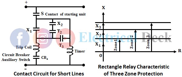
Reactance type relays are preferred for short-length lines. The impedance of a short line is small and the arc resistance value is proportional to the line impedance. Therefore, reactance relays are independent of arc resistance which makes them best suited for the protection of transmission lines of short length and more percentage of the line can be protected at high speed. The contact circuit of three-zone protection for reactance relay and its characteristics are given below.
The relay will operate when the reactance measured by the relay is less than the reactance for which the relay has been designed.
Three Zone Protection of Medium Length Lines :
Impedance type relay is used for lines of medium length. An impedance relay is a voltage restrained overcurrent relay as it measures distance by comparing the fault current I with voltage V across the fault point. The relay will operate if the impedance measured by the relay is less than the setting Z. The three-zone protection for the medium line and its characteristics are given below.
Three Zone Protection of Long Length Lines :
Mho-type relays are used for long lines. A Mho relay is a voltage restrained directional relay since the operating torque is obtained by the volt-ampere element and restraining torque is developed due to the voltage element. The three-zone protection and characteristics for long lines are given below.


