Translay protection is applied for the protection of transformer feeders. The name Translay refers to a relay with a transformer feature. It can be also used for the protection of single-phase or 3-phase feeder, and parallel feeders against both earth and phase faults.
This protection scheme works on the principle of circulating current that, under normal operating conditions the currents entering and leaving a feeder will be the same. But when there is a fault on the feeder, this condition doesn't exist and the difference between the currents entering and leaving is made to flow through a relay thereby isolating the feeder.
Translay Protection for Single Phase Feeder :
A simple form of translay protection for a single-phase feeder is shown in the below figure. It employs two current transformers at each end of the feeder to be protected. The relay used in this protection scheme is quite similar in construction to an overcurrent induction type relay. Two relays are used in this scheme and are connected to the two CTs.
The relay consists of two electromagnets, upper and lower that carry two coils, primary and secondary. The primary coils (P and P') of the two relays are energized from the secondaries of the current transformers connected in the phase of the line to be protected.
The upper magnets also carry secondary coils (S and S') which are connected in series with the operating coils (O and O') on the lower magnets of the two relays. The series connection is made such that the secondary coils are connected in opposition to the pilot wires.
Operation of Transley Protection :
The operation is based on the voltage balanced system, under normal operating conditions, the current at two ends of the feeder is equal and thereby flowing an equal amount of currents in both the primaries of the current transformers. Thus the primaries of two relays (i.e., coils P and P') carry the equal currents and induce equal voltages in the secondaries (i.e., in the coils S and S').
Since the latter coils are in opposition via pilot wires with the operating coils O and O', their induced voltages will be in opposition. Thus no current flows through the operating coils (O and O') and pilot wires. Thus no torque will be set up on the disc of either relay.
When a fault occurs on the feeder, the current flowing in the two CTs will be different inducing unequal voltages in the secondary coils. This sets up a circulating current in the secondary circuit and current will circulate between operating coils and pilot wires which set up a torque to be exerted on the disc of each relay.
Under the moment of such a torque, one of the relays closes the trip circuit contacts and the circuit breaker operates to disconnect the faulted section, while in the other relay the torque will hold the moment in the unoperated position. Therefore, under fault conditions, at least one component of either relay will operate and isolate the feeder.
Role of Copper Ring :
A copper ring is provided on the center limb of the upper magnet to provide compensation for pilot wire capacitance currents. It neutralizes the effect of pilot capacitive currents. Under normal operating conditions, thought the currents flowing in the two CTs are the same.
Due to pilot capacitive currents flowing in the pilot wires, it may lead to the production of torque. This current leads the secondary voltage by 90°. This problem can be eliminated by using copper rings by adjusting the angle between the induced current in the disc and the secondary current to be 90°.
Also, at the time external faults which involve high currents causes unbalance in the two current transformers and could circulate currents in the relay coils. The copper rings produce a restraining torque by these circulating currents and don't allow the disc of the relay to rotate. In addition, permanent magnets are fitted to provide eddy current damping of the discs which in turn further improves the relay performance.
Translay Protection for 3-Phase Feeder :
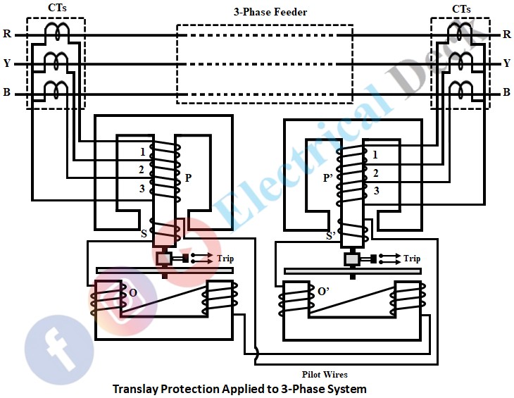
The below shows the protection scheme applied to a 3-phase transmission line to provide protection against phase-to-earth faults and faults between phases. Overcurrent induction type relays are used at both ends of the transmission line.
The relay consists of two electromagnets. The upper electromagnet consists of three primary coils energized from the secondaries of the current transformers connected to the phases of the lines to be protected and one secondary coil. The secondary coils on the upper magnet are connected in opposition whereas the secondaries on the lower magnet are connected in series through pilot wires.
The operation is similar to the single-phase translay system. Under normal operating conditions, the induced EMFs in the secondaries will be equal and due to the opposite connection of coils, no current flows through the pilot wires and operating coils. Thus the two relays remain inoperative. On the occurrence of a fault, the induced emf in the secondaries of the CTs will differ and thus current in the circuit.
Under such conditions, a circulating current will flow in the pilot circuit. Thus both upper and lower magnets of each relay get energized and a forward torque is exerted on each relay disc.
The primary coil is highly resistive and the current coil is highly inductive. Thus phase relation required between two fluxes for the production of torque is achieved. It is a good protection scheme up to a distance of 16km and has loop resistance of 800 ohms.


