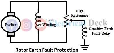
As the field circuit is operated ungrounded, a single ground fault will not cause much damage or affect the operation of the generator in any way. However, the probability of a second ground fault occurring is increased due to increased voltage stress to the ground which is quite dangerous.
In case a second ground fault occurs, a part of the field winding is bypassed, thereby increasing the current through the remaining portion of the field winding. This causes an unbalance in the rotor and may cause mechanical as well as thermal stresses resulting in damage to the rotor. In some cases, the vibrations have caused damage to bearings and the bending of the rotor shaft. Such failures have caused extensive damage.
Hence the protection system need not have to trip the entire system instead, it is used to indicate the occurrence of the first earth fault with the help of an alarm circuit so that, preventive measures are taken before the second earth fault occurs in the rotor. There are two methods for providing protection against rotor earth faults. They are,
- By using high resistance, and
- By ac and dc injection methods.
Rotor Earth Fault Protection By Using High Resistance :
In this method, a resistance is connected across the rotor circuit. Safe practice is to use protective relaying equipment to trip the main and field breakers as soon as the first ground fault occurs. To accomplish this, a sensitive earth fault relay (shown below) is connected between the mid-point of the high resistance potential across the field and the ground.
The disadvantage of this method is except for the center point, the relay operates for the earth faults for most of the rotor circuit. This field earth fault relay either gives an alarm warning or trips the machine.
Rotor Earth Fault Protection By AC and DC Injection Methods :
The modern method of providing protection against rotor earth faults includes ac injection or dc injection. The below figure shows the protection system provided in large turbo-alternators against earth fault in the rotor.
An auxiliary ac supply is connected across the primary winding of an auxiliary transformer. The output voltage of the transformer is rectified using a full bridge rectifier, and this rectified direct voltage is impressed between the positive pole of the field circuit and the earth through high resistance and the operating coil of the relay. The value of resistance is so chosen that, a sufficient amount of current flows through the operating coil of the relay for fault at any point on the field circuit.
The dc supply is preferred because it is simple to use and has no problem with leakage currents. In the case of the ac injection method, the high resistance is replaced by a capacitor. An instantaneous type relay is employed in this scheme which is connected to an alarm indication circuit.


