The relays whose operation is governed by the ratio of the applied voltage to current in the protected circuit is known as impedance relay. It is a distance relay that measures the distance by equating the fault current with voltage (which equates to impedance) across the fault loop and thus trips only for the faults on the line within the specified distance.
The measured impedance (i.e., V/I ratio) is the impedance between fault location on the line and relay location. Hence the measure of impedance is the function of line length or distance.
The relay operates when the ratio V/I (i.e., impedance) falls below the particular limiting value of the relay or equivalent distance for which the relay operates for the faults and is known as the reach of the relay. The operating time of these relays is constant, irrespective of the fault location within the protected zone. The impedance relays can be used for phase fault protection of lines of moderate lengths.
Principle of Operation of Impedance Relay :
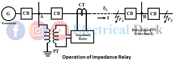
The below shows the basic principle of operation of an impedance relay. The voltage coil of the relay is connected to the line to be protected through a potential transformer. While current coil of the relay is excited by the current transformer connected in series with the line to be protected.
The current element of the relay produces the operating torque (positive torque) proportional to the operating current of the line. While the voltage element of the relay produces the restraining torque (negative torque) which is in opposition to the operating torque and proportional to the line voltage i.e., an impedance relay is a voltage restrained overcurrent relay.
Consider section AB of the line shown above to be protected. Let ZL be the impedance of the line when there is no fault i.e., under normal operating conditions. The relay is designed such that it operates when the ratio V/I falls below the preset value i.e., the impedance of the section to be protected falls below the preset value ZL.
Whenever a fault occurs in the portion of protected zone AB at point F1. The impedance Z between the point where the relay is connected and the point of the fault will be less than the predetermined value of ZL, and hence the relay operated. Consequently, the circuit breaker will open the circuit so that the line is protected.
Whenever a fault occurs beyond the protected zone at point F2. The impedance Z between the point where the relay is connected and the point of the fault will be more than the preset value ZL and hence the relay is inoperative.
Torque Equation of Impedance Relay :
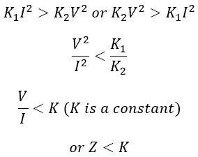
From the above, the positive torque produced due to the current element is proportional to I2 and the negative torque produced due to the voltage element is proportional to V2. If K3 is the torque due to the control spring. The torque equation of the electromagnetic type impedance relay is given by,
Since the effect of spring is small it can be neglected. Thus by putting K3 = 0, we get the torque equation as,T = K1 I2 - K2 V2For relay operation,
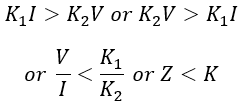
In the case of static and microprocessor-based relays, for the operation of the relay,
From the above equation, it can be seen that the impedance relay will operate only if the impedance (V/I ratio) seen by it is less than the preset value i.e., design impedance or given constant.
Operating Characteristics of Impedance Relay :
The operating characteristics of an impedance relay on the V-I plane are shown in the below figure. For a particular fault position, the impedance at that position is constant and varies with the variation in the fault position. If the fault is far away from the relay the V/I ratio will be higher and the ratio decreases as the distance between relay and fault decreases. Thus the relay operates for the faults in a particular section.
As seen from the above figure, the V-I characteristics of an impedance relay are slightly bent near the origin, this is due to the effect of the spring torque (spring effect) in electromagnetic types relays.
For microprocessor-based relay or static relay, the V-I characteristics will be a straight line. But in practice, for all the impedance relays, the curve at the origin is considered as the constant value of impedance. The impedance Z which is a preset value is given by,
The relay will operate for the values of Z in the positive torque region (i.e., less than the constant value represented by a straight line).
Operating Characteristics on R-X Diagram :
Other than the V-I plane shown above, the operating characteristics of the impedance relay can be more easily represented on the R-X plane shown below. The plane consists of resistance R on the x-axis and reactance X on the y-axis. Hence the plane is named as R-X plane.
From the above figure, Z = k represents a circle and Z < k indicates the area which lies inside the circle. The area within the circle is the operating region of the relay. The area outside the circle is the non-operating region.
The characteristics also depict that the relay is not directional i.e. if the fault point lies within the circle the relay will operate and send a tripping signal to the circuit breaker, no matter whether it is in the forward direction or in the reverse direction of the relay where it has been installed.
So, it is necessary that a directional relay is to be provided along with an impedance relay. Φ is the phase angle between V and I. As its characteristics are represented by a circle, the relay operates independently of the phase angle between V and I.
Since the relay operates for the magnitude of Z due to faults that occur in its protected section i.e., within the circle. Hence the area inside the circle is called the positive torque region, while the area outside the circle is called the negative torque region.
Directional Impedance Relay :
As seen above, a plan impedance relay is a non-directional relay, which operates for the faults in both forward and reverse directions. Such type of operation is undesirable and suffers from the following disadvantages,
- Discrimination between internal and external faults cannot be obtained as it operates for faults on either side.
- As it measures resistance and reactance, it is affected by arc resistance and resistance of transmission lines.
- It is affected by power surges as the circle covers a larger area on the R-X plane.
Therefore, to achieve discrimination between forward and reverse directions faults, a directional feature is provided for impedance relay. The directional unit restricts the tripping zone in the forward direction only.
Directional features to the impedance relay can be provided by using an impedance relay along with a directional unit. The directional feature restricts the tripping zone in the forward direction only, giving desirable operation. In impedance relay, a directional unit having straight-line characteristics is employed. The combined characteristics of directional relay and impedance relay are shown in the figure below.
DD' represents directional characteristics, OP represents the impedance of the line in the forward direction and OQ represents the impedance in the reverse direction. As the directional unit is added, the relay operates only for the positive torque represented by the shaded region i.e, the operating region of the relay.


