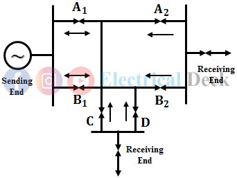
An overcurrent relay will operate for fault current flow in any direction, i.e., either in forward or in the reverse direction. In order to achieve the operation of the relay in the forward direction, a directional feature is added to the overcurrent relay by adding a directional relay to the overcurrent relay, such a relay will respond to fault flow in a particular direction.
Principle of Directional Overcurrent Relay :
A directional overcurrent relay operates on the same principle as that of an overcurrent relay. But in an overcurrent relay, the driving torque is developed due to the magnetic fields produced by the operating current of the circuit given through a current transformer.
While in the case of directional overcurrent relay the driving torque is developed due to the magnetic fields produced by both the operating current and voltage of the circuit in which it is connected for protection. The relay operates when the current exceeds a predetermined set value in a specified direction.
Construction of Directional Overcurrent Relay :
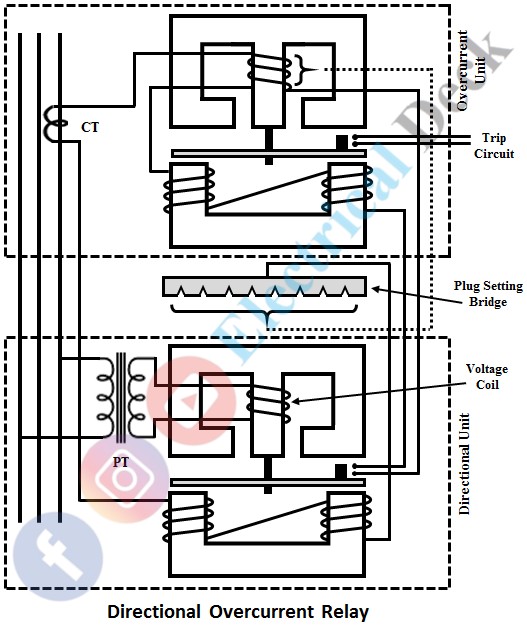
The schematic diagram of the directional overcurrent relay is shown in the figure given below. It consists of two relay units mounted in a common case, namely
- Directional relay unit, and
- Non-directional or overcurrent relay unit.
Directional Relay Unit :
The directional unit mainly consists of an induction cup relay with two opposite poles being fed by voltage and current. The potential coil on the upper electromagnet is connected to the system voltage through a potential transformer. The coil on the lower electromagnet is energized by the circuit current connected through a current transformer.
Voltage is taken as the polarizing quantity which remains more or less fixed when the other quantity i.e., the current undergoes wide changes in phase angle.
The two fluxes are produced by the two quantities for the production of torque. The contacts of the directional unit are connected in series with another winding over the lower magnet of the non-directional or overcurrent unit.
Non-directional or Overcurrent Relay Unit :
The overcurrent unit may be of either a shaded pole type or wattmeter type. The coil wound on the upper electromagnet of the overcurrent unit is tapped and connected to the circuit current through a current transformer.
The tappings are connected to a plug setting bridge to get the required current setting. An aluminum disc is placed between the two magnets which consist of moving contact that closes the fixed contact (trip circuit contacts) after the operations of the directional relay unit.
Working of Directional Overcurrent Relay :
During fault conditions, the fault current flows through the current coil of the relay which produces a flux in the lower magnet of the directional unit while the current in the voltage coil produces another flux in the upper magnet of the directional unit. The two fluxes produce a positive torque that tends to close its contact and operate the relay.
This in turn makes the relay current flow through the winding over the upper magnet of the overcurrent unit and therefore produces a flux in this magnet. This flux induces all the emf in the winding over the lower magnet of the overcurrent unit.
Since this winding is a closed path, the induced emf circulates a current which in turn produces another flux. The two fluxes produce a torque that makes the overcurrent relay trip the circuit breaker.
It is clear that the operation of the overcurrent relay is controlled by a directional unit. Therefore, the directional unit must operate first in order to operate the overcurrent relay.


