The speed (how fast is object moving) and direction of motion of an object or rate of displacement covered by an object traveling along a straight path is known as the Linear Velocity.
Most of the linear velocity transducers work on the principle of electromagnetic induction to measure the velocity. Based upon this principle, the velocity transducers for measuring the linear velocity can be classified as follows,
- Electromagnetic type velocity transducer
- Seismic type velocity transducer.
Electromagnetic Type Velocity Transducer :
Based upon the way of applying the principle of electromagnetic induction, the electromagnetic transducers can be classified into the following,
- Moving coil type or electrodynamic velocity transducer
- Moving magnet type velocity transducer
- Proximity type velocity transducer.
The electromagnetic transducer works on the principle that a voltage is produced in the coil due to a change of flux linkages resulting from a change in reluctance. As the rate of change of flux is directly proportional to the rate of change of reluctance, the voltage generated is directly proportional to the rate of change of reluctance i.e.,
As reluctance is a function of the length of the air gap, the voltage eo is directly proportional to the rate of change of the air gap (i.e., velocity).
1. Electrodynamic or Moving Coil Type Velocity Transducer :
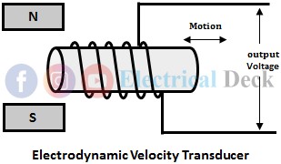
In this type of transducer, the magnet is fixed and the coil moves in the magnetic field, thereby resulting in the generation of voltage in the coil according to the electromagnetic induction principle.
The electrodynamic transducer consists of a fixed permanent magnet having an annular space between the poles as shown above. The coil is wound on a hollow cylinder. The hollow cylinder made up of a nonmagnetic material, is attached to the object whose velocity is to be measured.
When the object moves the coil cylinder moves in the annular space of the fixed magnet and a voltage is generated in the coil due to the change of flux. Therefore, the voltage generated is proportional to the velocity of the object.
Advantages of Moving Coil Type Velocity Transducer :
- It has a closed magnet circuit.
- The air gap is maintained constant.
- The effects of stray magnetic fields are reduced.
- These are highly stable devices even though temperature varies.
2. Moving Magnet Type Velocity Transducer :
This type of transducer makes use of a permanent magnet in the form of a rod. This rod is coupled to the object whose velocity is to be measured. The coil is so arranged that it surrounds the magnet during its motion as shown below.
When the object moves, the motion of the rod causes a change in flux due to a change in the air gap and a voltage is induced in the coil. This voltage is directly proportional to the velocity of the moving object. The direction of motion of the object can also be determined from the polarity of the output voltage.
Advantages of Moving Coil Type Velocity Transducer :
- It doesn't have any mechanical contacts. So, it requires less maintenance.
- The velocity and output voltage are linearly proportional.
- Manufacturing cost is low.
Disadvantages of Moving Coil Type Velocity Transducer :
- Its performance is affected by the stray magnetic field.
- It has a limited frequency response.
3. Proximity Type Velocity Transducer :
This method is a non-contact type method of measuring velocity. So it is required that the object whose velocity is to be measured is made up of a ferromagnetic material. The figure below shows the schematic of a proximity-type velocity transducer.
The coil is wound directly on a permanent magnet. The ferromagnetic object whose velocity is to be measured is placed near the poles of the permanent magnet. Due to the motion of the object with respect to the magnet, there is a change in flux Φ linking the coil, and a voltage is generated in the coil.
This voltage is directly proportional to the rate of change of flux (i.e., dΦ/dx) and hence the air gap between the face of the magnet and the ferromagnetic body.
Seismic Type Velocity Transducer :
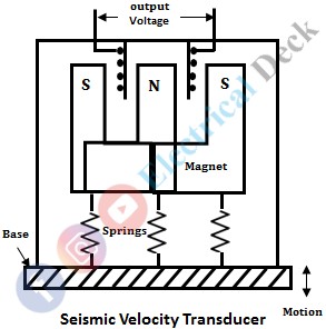
A seismic device (mass-spring system) can be used to measure the velocity. The electromagnetic induction principle in a seismic device can be brought into effect through either a movable magnet and a stationary coil or vice-versa. A schematic of the seismic velocity transducer is shown in the figure below.
In this transducer, the permanent magnet which forms the seismic of the system is supported to the base with the help of springs. The coil is fixed to the casing in such a way that the coil comes in contact with the magnetic lines of flux during the motion of the magnet. The seismic assembly is then attached to the object which is vibrating.
If the object vibrates at a frequency lower than the natural frequency of the seismic transducer, the magnet remains stationary. At frequencies above the natural frequency of the system, the magnet (seismic mass) undergoes a displacement equal to the displacement of the object. A voltage is induced in the coil due to the relative motion of the magnet with respect to the coil.
The velocity of the object can be determined from the output voltage as it is directly proportional to the rate of change of motion of the magnet relative to the motion of the base or coil.


