The Wien's bridge is an ac electrical circuit widely used for measuring frequency and can also be used for the measurement of capacitance with high accuracy. The bridge can be used even at high voltages but the circuit is sensitive to frequency. The Wien bridge has a combination of R-C series in one arm and a parallel combination in another arm.
Construction of Wien's Bridge :
The circuit consists of four arms, one arm with a series combination of resistor and capacitor and another with a parallel combination resistor and capacitor. The other two arms compress a resistance. The below shows the circuit diagram of Wien's bridge.
A balance detector or null indicator is connected across two junctions (i.e., across BD as shown above). The indicator shows null deflection when the bridge is balanced i.e. when the junctions B and D will be at the same potential.
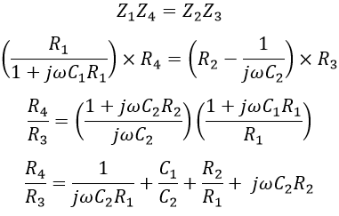
Let Z1, Z2, Z3, and Z4 be the impedances of the arm AB, AD, BC, and CD respectively and given as, When the bridge is balanced, we have, Equating the real terms, we get, The above equation is used to determine the resistance ratio (R4/R3). Now equating the imaginary terms, If suppose the bridge components are chosen such that R1 = R2 = R and C1 = C2 = C. Then the above equation is given as,
In order to maintain R1 = R2, a mechanical coupling is provided between them. So that R2 varies with R1 proportionally such that R1 = R2 can be maintained.
Applications of Wien's Bridge :
The above expression is used for the determination of the frequency of the applied voltage as well as capacitance. The capacitance is measured if the supply frequency is known. The frequency used in capacitance measurement is generally in the audio range i.e., 20 Hz to 20 kHz because at higher frequency the circuit gets damaged due to the effects of stray capacitance and loss in the capacitor.
It can also be used as a frequency determining element in audio and radio frequency oscillators, and harmonic distortion analyzer.


