Schering bridge is an ac bridge used for the measurement of capacitance, dielectric loss, and power factor of an unknown capacitor. It is the most popular and widely used method for measuring capacitance. The principle of operation is similar to other ac bridges i.e., balancing the bridge and comparing the unknown value with a known value.
Low Voltage Schering Bridge :
The circuit connection of a low voltage Schering bridge is as shown below. The arm AB consists of capacitor C1 in series with resistor R1. The resistor R1 represents the dielectric loss component of the capacitor C1.
The capacitor C2 is the standard capacitor and C4 is a variable one. The resistance R3 is a non-inductive resistance and R4 is a variable non-inductive resistance connected in parallel with a capacitor C4. The supply is connected between nodes A and C while the detector is connected between B and D.
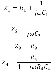
From the above figure, the impedances of the arms of the bridge are,Under balanced condition of the bridge, we have, Equating real and imaginary terms, we get, The phasor diagram of the Schering bridge under balanced condition is shown below. Now the dissipation factor of the capacitor under measurement is,
Generally, C2 and R4 are kept constant and balance is obtained by varying R3 and C4, so that the dissipation factor can be directly measured in terms of C4.
Limitations of Low Voltage Schering Bridge :
The LV Schering bridge suffers from the following disadvantages,- The calibration for the dissipation factor is useful only for one value of frequency. In order to use it for other frequencies, a correction has to be made by multiplying with the frequency ratio.
- The detector used is not so sensitive.
- It is quite difficult to obtain a balanced condition.
- Errors are present in the measurements of small capacitances using a low voltage Schering bridge.
High Voltage Schering Bridge :
The high voltage Schering bridge is mainly used for the measurement of small capacitances by using high voltage and high frequency. High voltage Schering bridge is the most suitable method for measurement at high voltage because of the following reasons,
- The results obtained using the Schering bridge for high voltage measurement will be very accurate.
- The circuit incorporates a vibration galvanometer as a detector which is highly sensitive.
- The errors due to earth capacitance are eliminated using Wagner's earth device.
- The circuit provides greater security for the operator.
- The power loss in the circuit resistance is very small.
It consists of a step-up transformer that supplies the required high voltage to the bridge from a normal ac supply as shown above. The capacitors C1 and C2 in the arms AB and AD are specially designed to withstand high voltages and have high impedances at normal supply frequency. The impedances of arms BC and CD are very low when compared with that of arms AB and AD.
The currents passing through the bridge will be very small due to high impedance, which results in low power consumption. This makes the bridge to use a sensitive detector (i.e., Vibration Galvanometer (VG)).
The voltage drops in the arms BC and CD will be very small as, the major part of voltage drops in arms AB and AD due to their high impedances. Point C is earthed, as the controlling elements are present in arms BC and CD, it assures the safety of the operating person. A spark gap is connected across each arm BC and CD to prevent high voltages in case of dielectric breakdown of C1 or C2.
Use of Spark Gap in Schering Bridge :
When the supply is given, very high voltage is impressed on the arms AB and AD, whereas a very low voltage appears across the arms BC and CD (since C is grounded). The two capacitors in AB and AD arms are subjected to very high voltage. Hence, there may be a chance of breaking down which results in high voltage in BC and CD arms.
But, the capacitor and resistors present in arms BC and CD are designed for low voltage and will get damaged. Hence, in order to avoid this, a spark gap is connected across these two arms. The spark gap is designed for a voltage of 100 V.
In case of any voltage greater than 100 V appears across the arms BC and CD. The spark gap gets activated and hence protecting the two LV arms from damage due to high voltages.


