Capacitive Transducer is a type of transducer or sensor that works on the principle of change in capacitance. It is a passive transducer (that requires external excitation for its operation or to produce output) with variable capacitance used to measure various physical quantities like displacement, pressure, force, etc.
Whenever the physical quantity to be measured is applied to the capacitive transducer, the change in input quantity applied causes a change in its capacitance value. Thus by measuring the change in the capacitance the input quantity applied can be determined.
Principle of Operation of Capacitive Transducer :
Capacitive Transducer operates on the principle of the capacitance of a parallel plate capacitor which is given by,
Where,- C = Capacitance of a capacitor in farads
- ε = εr ε0 = Permittivity of medium in F/m
- εr = Relative permittivity (dielectric constant)
- ε0 = Permittivity of free space (8.5 × 10⁻¹² F/m)
- d = Distance between two plates in m
- A = Overlapping area of two plates in m2.
From the above equation, we can conclude that the capacitance of a capacitor varies when,- The overlapping area A of the plates varies.
- The distance d between the two plates varies.
- The dielectric constant εr varies.
Hence, the variation in the capacitance of a capacitive transducer to measure physical or non-electrical quantities can be in the following ways,
i. Capacitive Transducer using the Effect of Variation of Overlapping Area of Plates :
From the equation of parallel plate capacitance, it is clear that the overlapping area of the two plates of a capacitor is directly proportional to its capacitance. Hence, the change in the area of the plates changes its capacitance linearly. Thus, it can understand that the displacement can be measured by this method.
The above figure shows the measurement of displacement by capacitive transducer due to the effect of variation in the area of plates. It consists of a fixed and movable plate. The movable plate moves when an external force is applied and causes to change its capacitance. This change in capacitance is measured and the amount of displacement can be determined. The linear displacement of about 1mm to 10mm can be measured by this method.
From the figure above, the capacitance of a parallel plate capacitor is,
Where l is the length of the overlapping area of plates and b is the width of the overlapping area of plates.
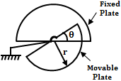
The principle of change in capacitance due to variation in the area of its plates can be used for measuring angular displacement. One such type of capacitive transducer used for measuring angular displacement is shown below.
As seen above it also consists of two plates, fixed and movable. Due to a change in the angular movement of the movable plate, the area between the two plates changes, thereby changing its capacitance. From the figure, we can say that the capacitance is maximum when two plates overlap each other i.e., at θ = 180°. Therefore, the maximum capacitance is,
If θ is the angular displacement, the value of capacitance at angle θ is given by, The sensitivity is given by, Therefore, the sensitivity is directly proportional to the area (∵ A = πr2 and ε, d are constant).
ii. Capacitive Transducer using the Effect of Variation in Distance Between the Plates :
In this method, the capacitance of the capacitive transducer is varied due to the variation in the distance between the two plates. We know that, if the distance between the two plates of a capacitor increases its capacitance decreases i.e., there exists an inverse relation between them. The below shows the measurement of displacement due to the change in the distance between the two plates.
The principle of operation is similar to the above method with fixed and movable plates. But here the applied displacement changes the distance between the two plates either by moving the movable plate towards the fixed plate or away from the fixed plate.
Hence the capacitance changes with inverse relation. Due to inverse relation, the response is non-linear, while it is linear in the above method. Thus small displacements can be measured by this method.
iii. Capacitive Transducer using the Effect of Variation of Dielectric Constant :
The measurement of displacement due to variation in the dielectric constant of a capacitor is shown below. It consists of two fixed plates with a dielectric medium between them. Here the dielectric medium is the movable element.
When the displacement to be measured is applied to the movable dielectric material. It moves with respect to the displacement applied. This causes to change in the dielectric constant and hence the capacitance.
If the dielectric material with relative permittivity εr is placed between the two plates. Initially, the capacitance of the transducer is,
When the dielectric material moves towards the left by distance x, the capacitance varies from C to ΔC. Thus the variation of capacitance is directly proportional to applied displacement.
Frequency Response of Capacitive Transducers :
An arrangement of capacitive transducers working on the principle of variation of capacitance due to variation of distance between plates is shown below.
Assume that, the distance between plates when stationary is xo. In this case, there is no flow of current and hence the output voltage is given by,
If there is any relative displacement xi from the position xo, some output voltage eo is produced. If the displacement is small with (xi/d) < 0.1, the following analysis can be carried out.
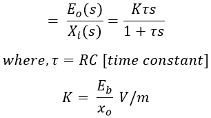
The transfer function, Therefore, the sinusoidal transfer function is, The amplitude ratio is, The frequency response plot is shown in the below figure.
From equation (1) it can be observed that the capacitive transducer circuit arrangement shown in the figure above is not suitable for static measurements because when, ω = 0, the output is zero. Also, it is not suitable for low-frequency applications because it produces inaccurate results (in low-frequency applications).
Hence, to obtain a high degree of accuracies this arrangement is best suited for high-frequency measurement applications ie., beyond ω1 frequencies. By examining the amplitude ratio and phase shift i.e., equation (1) and (2) we can write,
In this way, the magnitude ratio and phase shift are constants and do not depend on frequency. Therefore, at low frequencies to make ω𝜏 >> 1, the 𝜏 value should be made large. We have 𝜏 = RC, which means for a given capacitive transducer by increasing the resistance value R the value of 𝜏 is increased. This value of resistance can be 1 MΩ or more.


