The AC Bridges are the alternating current electrical circuits used to find or measure the unknown resistance, inductance, and capacitance. These are basically measuring instruments similar to DC Bridges (e.g. Wheatstone bridge, Kelvin's bridge, etc) and only works with ac supply.
The principle of operation is based on the comparison measurement method i.e., comparing the unknown value to be determined with the known value when the bridge circuit is balanced.
Construction of AC Bridge :
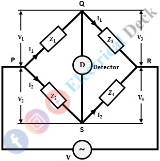
The ac bridge mainly consists of four arms with four impedances (each arm consists of an impedance) and a balance detector. The four arms are connected in such a way that, it forms a closed circuit with four junctions. In the four impedances of the bridge, one of them is unknown (which is to be determined) and the remaining are known impedances. The below shows the general ac bridge circuit.
An ac voltage source at the required frequency is connected across two opposite junctions and a balance detector across the other two opposite junctions. The balance detector used is headphones or vibration galvanometers depending upon the frequency of the supply.
Mostly vibrational galvanometers are used for balance detectors in ac bridges. Because vibrational galvanometers are tuned detectors i.e., they respond only to the fundamental frequency for which they are tuned.
In the case of ac bridges, frequency and supply waveform plays a very important role. If the input waveform is perfect and does not contain any harmonics then the balancing condition for bridges can be obtained easily. But, if the supply waveform contains any harmonics, it will be very difficult to obtain the balance condition.
Thus the variation in the frequency will once again create problems for obtaining balance condition (since the balance equation in ac bridges is a function of frequency). The above problems can be eliminated by using a vibrational galvanometer as a detector in the case of ac bridges. The vibrational galvanometer will give deflection for resonant frequency and hence will not respond to other frequencies and harmonics.
Conditions for Balancing of AC Bridge :
In order to measure unknown resistance, inductance, or capacitance connected to one arm. At first, the bridge is to be balanced. For balancing of the bridge, no current should pass through the detector. This condition is obtained when the potential difference across the detector is zero (i.e., across points Q and S). If ac source potential be V and the potential drops across Z1, Z2, Z3, and Z4 be V1, V2, V3, and V4 respectively.
Thus, at when the bridge is balanced,V1 = V2 ...(1)V3 = V4 ...(2)
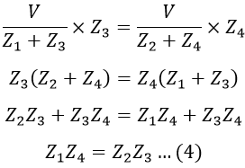
Consider equation 2, i.e., V3 = V4,
Substituting the values of I1 and I2 in equation 3, we get,
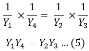
We know that, Z = 1/Y. Therefore, for the balance of the bridge, equation 4 can also be written in admittance form as,
The equation 4 can be written in polar form as,
Similarly, equation 5 can be written in polar form as,
Therefore, from the above equation, the conditions for balancing ac bridges are,- The magnitude of impedance or admittances should satisfy the relation.Z1 Z4 = Z2 Z3
- The phase angles of impedances or admittances should satisfy the relation.θ1 θ4 = θ2 θ3
Measurement of Resistance, Inductance, and Capacitance Using AC Bridge :
Let us consider an ac bridge with four arms and a detector as shown below.
Let,- L1 = Unknown inductance to be measured
- R1 = Internal resistance of the unknown inductor
- L2 = Standard known inductance
- R2, R3 & R4 = Standard non-inductive resistances.
From the balance condition of the bridge, we know that,
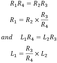
Equating real and imaginary parts on both sides, we get,
Hence both the values of R1 and L1 depend upon the ratio of R3 and R4 (i.e., R3/R4). So, if we choose R3 and R4 as variable elements, then to obtain balance once R3 is adjusted then R4 is adjusted and again R3 is adjusted till the bridge comes nearer to balance then R4 is adjusted.
In this way, the balance point shifts or slides with the number of adjustments of R3 and R4. This is termed has sliding balance. Hence, if we choose R3 and R4 as variable elements then the two balancing equations will be dependent and convergence of balance becomes very poor and thus the sliding balance effect appears.
So, in order to satisfy both the balance equations and for convenience of manipulation only one element is chosen as the variable for one balance equation. So that the two balance equations are independent of each other. As R2 and L2 appear in different balance equations, they can be selected as variable elements.
Thus L2 and R2 are varied alternatively till the balance is obtained. By this, the condition of interaction between two controls is avoided. Also, the convergence to balance point is best as both R2 and L2 are in the same arm.
Errors in AC Bridges :
The different sources of errors in AC bridges are,
Stray Conductance Effects :
If there is no proper insulation between various components of a bridge circuit, errors may arise because of leakage currents from one arm to another. This mainly happens for a high impedance bridge. To overcome this variable components and other pieces of apparatus are mounted on an insulating stand.
Eddy Current Errors :
The induced eddy currents in the standard resistors and inductors change the standard values of the bridge, causing errors. To avoid such errors. The materials with large conductivity masses should not be placed near the bridge.
Errors due to Electrostatic Coupling :
The Inter-capacitance effect arises if the adjacent branches of a bridge network are at a different potential. In other words, the electric field of the branches interacts thus introducing errors. Effective shielding by means of covering elements with earthed metallic shields can minimize this error.
Errors due to Electromagnetic Coupling :
If there is electromagnetic coupling between the source and detector, an emf is induced in the detector directly from the source. The zero indication of the detector is obtained only when the bridge supplies the voltage which is equal in magnitude and opposite in phase as that of induced emf.
Residual Errors :
Residues mean small inherent inductance or capacitance that are used in bridge circuits and are assumed to be non-inductive and non-capacitive but in practice, their inductance and capacitance are never zero. So, it is necessary to evaluate these components otherwise these errors will creep in.
Frequency Errors :
The frequency of the supply system plays a vital role in causing errors in the supply system i.e., the presence of harmonics in supply causes variations in the sinusoidal waveform due to which the appreciable crosses are generated.


