When there is the existence of inductance and capacitance in the circuit. Due to energy storing property of inductor and capacitor, it causes voltage and current to become out of phase. In order to overcome this phase shift, there is a need for extra power known as Reactive Power. It is denoted by Q and expressed in volt-amperes reactive (VAR). The formula for reactive power is given as,
The reactive power measurement is often essential to determine the nature of load and in the measurement of power factor. Let us see the measurement of reactive power in single-phase and three-phase circuits.
Measurement of Reactive Power in Single Phase Circuit :
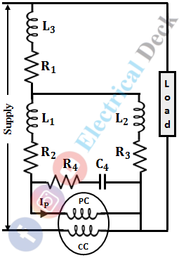
A single-phase varmeter (volt-ampere reactive meter) is used to measure reactive power in single-phase circuits. Basically, it is an electrodynamic instrument, in which the voltage coil is made highly inductive reactance i.e., by replacing voltage coil resistance with an inductor. The below shows the circuit diagram of a single-phase varmeter.
Due to inductance, the current in the voltage coil is in quadrature with its voltage (i.e., current lags 90° behind voltage). This causes the meter to indicate,
The drawback of a single-phase varmeter is that, errors are introduced due to the presence of harmonics and when the instrument is operated other than the frequency for which it is adjusted. Also, it can be not used in circuits operating at high voltages.
Measurement of Reactive Power in Three Phase Circuit :
Three Phase Balanced Load :
In three-phase circuits, when balanced loads are connected then the reactive power measured will be same in all the phases. Hence, only a single wattmeter is required to measure the reactive power.
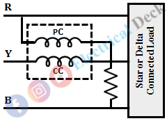
In order to measure the reactive power, a current coil is inserted in any one phase and the voltage coil is connected across the remaining two phases as shown below.
Consider, the pressure coil is connected in between phases R and B, and the current coil is inserted in phase Y.
Let,- VR, VY, VB = RMS value of voltages in phases R, Y, B respectively
- IR, IY, IB = RMS value of currents in phases R, Y, B respectively
- Φ = Phase angle between respective voltage and current.
Now, for a balanced load we have,VR = VY = VB = VL = √3VP (star connected)and IR = IY = IB = IL = IP (star connected)Therefore, the reactive power or the wattmeter reading per phase is the product of voltage, current, and cosine of the angle between them i.e.,Q = VL IL cos ΦQ = √3VP IP cos ΦBut from the phasor diagram, the angle between the pressure coil voltage and current coil current is 90 + Φ. Therefore,
Therefore, the total reactive power = 3 VP IP sin Φ = -√3 × Q, and the phase angle Φ is given by,
Three Phase Unbalanced Load :
In three-phase circuits, when unbalanced loads are connected then the reactive power measured in each phase will be different. Hence, the reactive power in unbalanced loads is determined by using the two-wattmeter method and the three-wattmeter method.
For balanced load conditions, the reactive power is given as,
The above equation is slightly different in unbalanced loads. In balanced loads, the instantaneous quality is equal to the reactive power. But under unbalanced loads, reactive power will be equal to its average power. The reactive power under unbalanced loads is given as,


