The Loss of Charge Method is used to measure resistance greater than 100KΩ or 0.1MΩ. The drawback of the Wheatstone bridge is that, it cannot be used to measure the high value of resistance of the order of 1MΩ because of the reduction in the sensitivity to unbalance caused by the high resistance values. Also, the high resistance measurements are inaccurate due to leakage over the insulation of the bridge arms.
Hence, in order to avoid the above problems while doing high resistance measurement the following methods are used.
- A modified Wheatstone bridge with a guard circuit can be used.
- Other methods for high resistance measurements like,
- Loss of Charge Method
- Direct Deflection Method
- Megohm bridge Method
- Megger
In this let us see about the measurement of high resistance using the Loss of Charge Method.
- Loss of Charge Method
- Direct Deflection Method
- Megohm bridge Method
- Megger
Loss of Charge Method :
This method is especially used for the measurement of the very high value of resistance like the insulation resistance of cables and machines, high resistance circuits like vacuum tubes, leakage resistance of the capacitor, the surface resistivity of the material, and insulation resistance of the transformer windings. The basic idea is based on the charging and discharging, of a known value capacitor.
The figure above shows the circuit connections for the loss of charge method. Where, R is the unknown resistance to be measured, C is a known value capacitor placed across R, V is an electrostatic type voltmeter to measure the voltage across the parallel combination of R and C.
The circuit is driven by a battery having a voltage V. S1 and S2 are the switches used for charging and discharging the capacitor. It is assumed that the internal resistance of the voltmeter and leakage resistance of the capacitor is infinite. The sequence of operation can be explained as follows,
When Switch S1 Closed and S2 Open :
With switch S1 closed and S2 open, the capacitor charges to a particular voltage. The voltage across C is measured by the voltmeter V and is noted down.
When Switch S1 Open and S2 Closed :
With switch S1 open and S2 closed, the battery is disconnected and the unknown resistance R gets connected across C. Now the capacitor discharges through R. During this, the capacitor voltage is measured by the voltmeter.
Taking the above two readings of voltmeter, we get two equations solving the two equations, the value of unknown resistance can be determined.
Derivation :
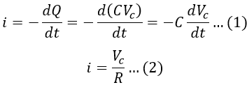
If Vc be the terminal voltage of the capacitor consisting of capacitance C farad (assumed to be lossless) and Q (coulomb) be the charge at time t (secs). Then the charging current i is,
Equating equations 1 and 2, we get, Applying integration on both sides, we get, Applying initial conditions to the above equation. At t = 0, Vc = V (i.e., the voltage at which capacitor is initially charged), therefore,
The below graph shows the variation of Vc with respect to t. If the value of the resistance to be measured is very large, then the time taken for the voltage to fall is quite large. Hence, this method is tedious and time consuming.
However, the accuracy of the voltage measured depends upon methods implemented to reduce errors. Otherwise, errors are introduced while computing the ratio (E/V), thereby causing an error in the measurement of insulation resistance. In order to obtain high accuracy, a drop in voltage i.e., (V - Vc) is taken instead of Vc.
Errors in Loss of Charge Method :
There are certain possible errors in the loss of charge method. The errors must be minimized, otherwise, an appreciable amount of error is introduced while measuring insulation resistance.
Error due to Leakage and Absorption
Every insulating body will have some leakage current since we can't get an ideal insulator. The value of this leakage current is quite significant with respect to the current under measurement. Due to this, the results will not be accurate. Hence in order to reduce the error due to leakage, the insulation resistance of the capacitor and voltmeter must be very high.
Also, every insulation material will have an absorption effect. The net current flowing is the sum of currents due to resistance and absorption. Again due to this effect, the readings will have an error. In order to reduce it, the observation should be taken for a long period of time.
Error due to Variation in Insulation Resistance due to Variation in Temperature :
The resistance of insulating material is a function of temperature. Whenever the temperature increases, the resistance decreases, and hence the current flowing through the material increases. As we know that the temperature is a variable quantity.
Therefore, the resistance, as well as current, vary along with it. Hence in order to have accurate results, resistance along with the temperature at which the test was performed must be specified.
Error due to Time of Application of Voltage :
The effect of absorption is associated with almost all the insulating materials. The value of current due to absorption effect is not constant but varies with the time for which voltage is applied. The value of the absorption current is different at a different instances of time. Hence due to this accuracy of the measurement will be lost.


