Basically, electrostatic instruments are used only as voltmeters which can measure the voltages both in ac and dc circuits. The extension of range of electrostatic voltmeters can be done using,
- Resistance potential divider
- Capacitance potential divider
Resistance Potential Divider :
Resistance potential divider is a highly noninductive resistance across which the voltage to be measured is applied. An electrostatic voltmeter with capacitance C is connected across a portion of resistor R. It can be used both for dc and ac voltages. The arrangement of the resistance potential divider is shown below.
In the above figure,- Vm = Voltage under measurement.
- R = Non-inductive resistance
- r = Resistance to which an electrostatic voltmeter is connected
- E = Electrostatic voltmeter
- C = Capacitance of an electrostatic voltmeter
- Ve = Voltage across an electrostatic voltmeter
The portion of the non-inductive resistance to which an electrostatic voltmeter is connected is called a multiplier. By varying the resistance r of the portion to which an electrostatic voltmeter is connected, the range of the electrostatic meter can be extended. As it can be used for both dc and ac circuits, we have,
Multiplying Factor for DC Circuits :
Multiplying factor m is defined as the ratio of voltage under measurements to the voltage across an electrostatic voltmeter.
In dc circuits, as frequency is zero, the capacitive reactance is infinite (i.e., XC = 1/0). Hence in dc circuits, the total impedance of the potential divider is R itself. From the above equation,
Multiplying Factor for AC Circuits :
In ac circuits, the resistance of the potential divider contains reactance along with the resistance. As resistance r and C are connected in parallel, the equivalent impedance is given by,
The total impedance of the potential divider is given by, So, the multiplying factor m (factor by which change in voltage due to potential divider) is given by, Magnitude of multiplying factor m is,
This type of method is mostly used for dc measurements and low voltage ac measurements. This method is not suitable for high voltages due to excessive power loss and the readings are affected by stray capacitance.
Capacitance Potential Divider :
Capacitance potential divider can be used for ac voltages only. In this divider, capacitors are used for extension of the range of electrostatic voltmeters. These capacitors can be connected in two ways across an electrostatic voltmeter. A single capacitor is connected in series with the electrostatic voltmeter or a number of capacitors that are connected in series are present, to which the electrostatic voltmeter is connected in parallel.
When Electrostatic Voltmeter is connected in Series with Capacitor C1 :
In the above figure,- C1 = Capacitor
- Ce = Capacitance of an electrostatic voltmeter
- Vm = Voltage under measurement
- Ve = Voltage across an electrostatic voltmeter
As the capacitors C1 and Ce are connected in series, the equivalent capacitance Ceq is given by,
The total impedance of the capacitance potential divider is given by,
The impedance of the voltmeter is given by,
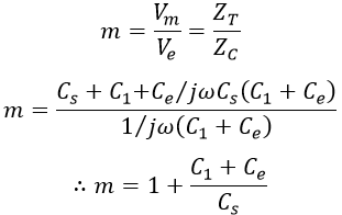
The multiplying factor is defined as the ratio of voltages of the potential divider to the voltage across the electrostatic voltmeter is given by,
When Electrostatic Voltmeter is connected in Parallel Against a Combination of Series Capacitors :
In the above figure, C1, C2,... Cn is the capacitors arranged in the circuit. Where,- Ce = Capacitance of an electrostatic voltmeter
- Ve = Voltage across voltmeter
- Vm = Voltage under measurement
Let Cs be the equivalent capacitance of capacitor C1, C2,...Cn connected in series. In the above figure, as capacitors C1 and Ce are connected in parallel, equivalent capacitance Ceq is given by,


