The various types of errors in an energy meter are caused by the driving system and braking system.
Errors Caused by Driving System :
- Errors due to the incorrect magnitude of fluxes. These are mainly due to variations in supply voltage or load current. The flux produced by the shunt magnet varies with variations in supply frequency or coil resistance.
- Incorrect phase angles between various parameters like induced emf, current, and flux. These are mainly due to variation in supply frequency, incorrect lag adjustments, change in resistance of coils with temperature, etc.
- Lack of symmetry in the magnetic circuit. Due to this, driving torque is produced in the disc even with no current flowing through the current coil, and hence the meter creeps.
Errors Caused by Braking System :
- Change in the strength of brake magnet due to variations in temperature etc.
- Self-braking effect of series magnet flux due to overcurrent (or loads).
- Variations in disc resistance with temperature.
- Friction errors at light loads.
Various Adjustments for Compensations of Errors :
There are various adjustments made to the energy meter to overcome the errors mentioned above. They are,
Light Load Adjustment :
This compensation is to overcome the frictional errors, which are high during low loads. During light loads, the torque produced in the disc is insufficient to overcome the frictional torque, which is high during starting rather than running.
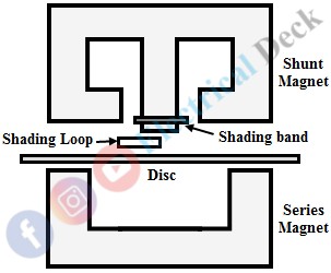
For this compensation, a shading loop is placed in the air gap between the shunt magnet and the disc, so as to cover a region of the center limb and a pole of the shunt magnet as shown in the figure above.
The shading loop is energized proportional to the supply voltage and the field due to this loop produces more starting torque, which is enough to overcome the frictional torque at the starting. Its effect is negligible during running conditions. The starting torque can be adjusted to the required value by the lateral movement of the shading loop.
Creeping Adjustment :
Due to the above friction compensation, the meter may creep sometimes on no-loads. This is because the starting torque provided by the shading loop is irrespective of load current. To compensate this effect, two holes are drilled opposite to each other on the disc. When a hole comes under a pole of shunt magnet, the disc tends to remain stationary in that position.
Instead of drilling holes, a small piece of iron can be placed on the disc and when the iron piece comes near the brake magnet, it is attracted and make the disc stop.
Lag or Power Factor Adjustment :
This compensation is provided to overcome the errors due to incorrect phase angle between the supply voltage and shunt magnet flux φp. To bring φp exactly in quadrature with supply voltage two types of lag adjusting devices are available. They are,- Shading coil
- Shading band
These devices are placed on the center limb of the shunt magnet, so as to link with φp. The shading coil or lag coil circuit is closed through a low variable resistance, by which the lag angle φp can be varied. In the case of the shading band, the band is moved along the axis of the shunt magnet to bring φp in exact quadrature with voltage.
Overload Compensation :
This compensation overcomes the effect of self-braking. The self-braking effect is due to the overcurrents through the series magnet, which results in more amount of dynamically induced EMFs in the disc.
This increases the eddy currents in the disc, which produces a self-braking torque. To prevent this self-braking action the rated rpm of the disc is kept low and the series magnetic flux φs is made smaller than φp. Hence the effect of dynamically induced EMFs over statically induced ones is negligible.
Along with the above adjustment a magnetic shunt is provided for a series magnet to divert the path of some amount of flux as shown in the above figure. φs is the total series magnet flux, φd is the diverted flux and φs' is the flux involving in the operation of the meter. The saturation point of the magnetic shunt is kept lower.
Voltage Compensation :
This compensation overcomes the errors due to overvoltages in the supply. The effects due to overvoltages are saturation of iron parts in the meter and self-braking effect due to increase in φp, which increases the dynamically induced EMFs in the disc.
To overcome these effects a saturable magnetic shunt is provided for the shunt magnet and the reluctance of the side limbs is increased by providing air gaps in between (i.e., by providing holes).
Temperature Compensation :
An increase in temperature results in an increase in resistance of the coils and the disc, and a decrease in the braking magnetic field. So, the overall effects result in an increase in the speed of the disc.
To compensate this error, a temperature shunt is provided on the brake magnet so that, its field would not become weak with the increase in temperature. Hence, the braking torque remains constant at all temperatures, which controls the speed of the disc.
Speed Error :
Sometimes there is a need for speed adjustment of the disc in order to get an accurate measurement. The speed of the disc depends on the braking magnet. We know that the movement of the rotating disc through the magnetic field crossing the air gap sets up eddy currents in the disc. These eddy currents when interacts with the magnetic field produced by the braking magnetic produce a braking torque on the disc.
Therefore, by changing the position of the braking magnet the speed of the rotating disc can be controlled. If the meter runs fast, the braking magnet will be moved away from the center of the disc, which increases the radius, which in turn decreases the speed of the disc. Thus the disc obtains a steady speed.


