Energy meter calibration is a process required to determine and reduce the error when the energy is measured. The errors in the energy meter can be caused by different sources like voltage transformers, current transformers errors due to phase angle, crystal oscillators, etc.
Theory for Energy Meter Calibration :
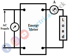
Energy meters have specified characteristic constants, which give information about the number of revolutions of the disc and the measured energy in joules. These characteristic constants are given by the manufacturer. The experimental setup of the energy meter calibration is shown in the figure below.
Before carrying out the calibration process, different adjustments such as load adjustments, lag adjustments, creep adjustments, etc., are done on the energy meters.
Generally, the number of revolutions is usually high which cannot be taken into measurement in the laboratories. Thus consider the number of revolutions (m) in the disc as 10 for the energy of n joules by using the characteristic constant. The energy (E) can be computed from 'm' is given as,
The meter possesses no error if the energy calibrated for 10 revolutions should be equal to the energy taken by the load for the same amount of revolutions and time. Energy taken by the load or true energy is denoted as ET. The loads applied to the energy meter are varied and the time taken for the 10 revolutions is measured using a stopwatch. The parameters such as voltage, current are observed from the circuit and are tabulated as given below,
| S.No. | Voltage (V) | Current (A) | Power (p) watts | Energy E1 = PTJ | % Error |
|---|
| Readings observed from the test |
For the specified revolutions (i.e., 10) the energy E is constant whereas energy consumed by load ET gets varied and is determined theoretically. Therefore, under various load, the percentage error is calculated as,
Calibration Curve :
Calibration of energy meter can be obtained graphically by plotting the percentage error against load current I. This graphical representation of the calibration process is called a calibration error. At the initial stage, the load current I is zero, and hence no % error because the energies E and ET are zero. The calibration curve is shown in the figure below.
The % error obtained can be positive and negative. The limits of the load current error are easily determined by observing the calibration curve. If the limit is not under desired range then the error can be made to a minimal value by applying different adjustments such as lag, friction, creep adjustments.


