In the last article, we have seen about single phase electrodynamometer type wattmeter and how it is used for measuring power in both ac and dc circuits. Now, let us learn about a 3-phase electrodynamometer type wattmeter for the measurement of 3-phase power.
Working of 3-Phase Electrodynamometer Wattmeter :
The 3-phase dynamometer wattmeter is similar in construction to that of a single-phase dynamometer wattmeter. The only difference is it consists of two fixed coils and two moving coils.
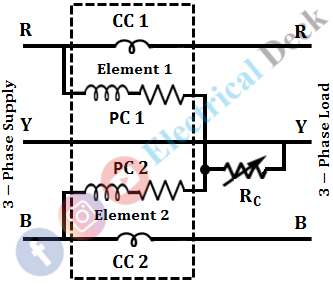
Fixed coils are connected in series with lines and moving coils are connected across the lines. Hence, the fixed coils are known as current coils (CC 1 & CC 2 ), and moving coils are known as pressure coils or voltage coils (PC 1 & PC 2). The below figure shows the arrangement of a 3-phase wattmeter.
The combination of a fixed coil and a moving coil is called an element. So, the 3-phase dynamometer wattmeter consists of two elements. Both the voltage coils are mounted on a single spindle, (so as to integrate the power measured by each element). The connections of the 3-phase dynamometer wattmeter are exactly similar to that of the 3-phase power measurement using two single-phase wattmeters as shown in the figure below.
In two wattmeter method, the total power consumed will be the sum of the readings of both the wattmeters, which has to be calculated manually. Whereas, in a 3-phase electrodynamometer wattmeter, the total power consumption is indicated directly, as the power consumption noticed by both the elements is being integrated internally.
The complete arrangement just behaves as that of two wattmeter method of power measurement. Each set of moving coil and current coils will experience a torque which is proportional to the power measured by that set. Hence, the net torque is the sum of deflecting torque of the two,
Hence, the total deflecting torque of the two sets is proportional to the total power measured by the circuit.
Elimination of Mutual Effect Between the Two Elements of the Wattmeter :
The power measured by the meter will be correct only when there is no interaction between the fields of both the elements i.e., only when the mutual effect between the two elements is absent. This can be achieved by placing an iron shield in between the elements.
Further, the presence of any mutual effect will be compensated by connecting a variable resistor called compensating resistor Rc in series with the pressure coils as shown in the figure below.
This method of compensating the mutual effect is called Weston's method. By varying the resistor Rc the currents through the pressure coils are varied which in turn varies the fields, so as to compensate for the mutual effect.
Necessity of Pressure Coil to be Purely Resistive :
The electrodynamometer type wattmeter consists of two coils i.e., the current coil and pressure coil. The current coil should carry the full line current and hence, it will be connected in series with the line whereas the pressure coil will be connected across the line.
The resistance of the current coil should be very less so that, the whole of the current flows through it with fewer losses, whereas the resistance of the pressure coil should be very high compared to its inductive reactance because of the two reasons.
- Very high resistance such that a very small current flows through it and hence less I2 R loss.
- If the resistance is very high when compared to its reactance, the current will be almost in phase with the voltage on the other hand if the resistance is less, the current will lag behind the voltage with a greater angle and hence this will introduce an error in the readings of the instrument.
Hence from the above two reasons, the pressure coil should be purely resistive i.e., the resistance of the coil should be very high compared to its inductive reactance.
Shape of Scale of Electrodynamometer Wattmeter :
In electrodynamometer wattmeters, the final steady deflection θ is given by,
From the above equation, it is clear that the deflection θ is directly proportional to the power (i.e., VI cosθ) which is being measured. Hence, the scale of the electrodynamometer wattmeter is uniform i.e., these instruments exhibit a pure Square Law Response over the interval in which dM/dθ is constant. The shape of the scale of electrodynamometer wattmeter is shown below.
In a dynamometer wattmeter, a parallel field is obtained. In the parallel field, the value of dM/dθ is not constant. Hence, the value of dM/dθ which is assumed to be constant in practice is not true. In these instruments, the mutual inductance M which is present between the fixed and moving coil depend on the position of the moving coil.
When θ = 180°, M is maximum. So, by proper design, M can be made to change over a range of 40° to 50° on either side of the zero mutual inductance. Here, the deflection θ varies from about 80° to 100° as M varies from 40° to 50°.
Due to less change in the value of M, dM/dθ is assumed to be constant in practice. Hence, the scale is uniform over the range of 80° to 100° of θ. In this range, the wattmeter exhibits a pure square law response.


