A potentiometer is a device that measures the value of an unknown voltage. The working principle is based on the comparison of an unknown voltage with a known voltage. Potentiometers are the most commonly used devices for measurements because of their high accuracy.
Construction of Slide Wire Potentiometer :
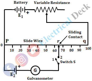
The below figure shows the connection of a basic slide wire dc potentiometer. It consists of a slide wire made up of manganin or german silver of predefined length and uniform cross-section, hence it contains uniform resistance throughout the length of the wire.
A battery is connected to the slide wire through a variable resistor R. A meter scale is placed along the slide wire to measure the position of the sliding contact. A galvanometer is used as a null detector to compare the unknown voltage with the known voltage. Switch S is used to connect the known and unknown emfs alternately.
Working of Slide Wire Potentiometer :
When the switch S is in position 1, the battery supplies current to the sliding wire. This current through the slide wire is varied by connecting a variable resistance in series with the battery. The current is adjusted to value until the galvanometer shows zero deflection.
Let L1 be the length of the sliding wire corresponding to zero deflection of the galvanometer. Now, consider the switch S in position 2, with this position, the unknown emf is connected in the circuit.
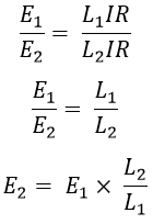
Now, adjust the slide wire such that, the galvanometer again shows zero deflection. The zero deflection of the galvanometer indicates that the two emfs are equal. Let L2 be the length of the sliding wire corresponding to the zero position of the galvanometer. Let E1 and E2 be the known and unknown emfs respectively. Then from the above analysis, the balance equations are,
Where,- I = Current through the slide wire
- R = Resistance of the slide wire
From the above two equations, we get,
Hence, from the above equation, the value of unknown emf E2 can be found by knowing the length of the sliding wire with switch positions 1 and 2. However, some precautions must be taken while using a potentiometer. They are,- The capacity of the known emf E1 must be sufficient enough to provide a constant current through the sliding wire during the operation.
- The accuracy of potentiometer measurement depends on the accuracy with which the ratio L1/L2 is determined. Hence, to have higher accuracy, a very long sliding wire should be used.
- In order to protect the galvanometer, resistance must be connected in series with it.
Standardization of Potentiometer :
The term standardization means making the meter as a direct reading one, by adjusting the current through the slide wire due to the battery voltage. Standardization is defined as the process of adjusting the working current of the potentiometer such that the voltage drop across the section of slide wire is equal to the standard reference voltage. The circuit diagram for standardizing a basic dc potentiometer is shown below.
When SPDT is in operate position and the galvanometer switch is kept open, then the working current supplied by the battery reaches the slide wire and flows through it. When the galvanometer switch is closed, unknown emf E which is to be measured is connected in the circuit.
The voltage drop across the sliding wire can be varied by moving the sliding contact. When unknown voltage E becomes equal to the voltage drop E1 across the portion ac of slide wire, then the galvanometer shows zero deflection.
Hence, the value of unknown emf E can be measured by finding the voltage drop E1 across ac of slide wire. In this method, sliding contact is moved to vary the working current to match the voltage drop across slide wire against a standard reference voltage source. This process is known as "standardization".
When the SPDT is switched to calibrate position, then a potentiometer can be calibrated. Here, at this position the Weston standard cell (i.e., Vs = 1.0186) gets connected in the circuit. The sliding contact of the sliding wire is placed at 101.86cm on the scale. The rheostat is varied in order to change the working current in the slide wire such that the galvanometer shows null deflection.
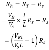
When the galvanometer does not deflect, it means that the voltage drop across the slide wire is equal to the voltage of the standard cell. The equation for working current of the slide wire and the rheostat setting is given by,


