A potentiometer is a device used for measuring the emf of a cell or potential difference between two points in a circuit. It works on the principle of comparison i.e., comparing the unknown voltage with the known voltage and makes use of balanced condition.
DC Crompton's Potentiometer :
DC Crompton's potentiometer is the laboratory-type potentiometer that is used to measure unknown emf effectively with a great degree of precision.
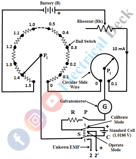
DC Crompton's potentiometer works on the principle of a slide wire potentiometer. In other words, the DC Crompton potentiometer is a modified version of a slide-wire potentiometer. It basically consists of a small slide wire which is circular in shape and a dial switch with calibrated resistors, as shown in the figure below.
In the figure shown,- B = Battery
- Rh = Rheostat
- G = Galvanometer
- R = Protective resistance which is of order of 10 KΩ
- S = Double throw switch
- C = Standard cell
In DC Crompton's potentiometer, the dial switch is divided into fifteen steps with each step having a resistance of 10Ω. Hence, the total resistance of dial switch is equal to 150Ω (15 X 10 = 150). The slide wire is in the form of a circular wire and has a resistance of 10Ω, with a single turn. A double-throw switch is provided for standardization and for measuring the unknown emf, one after the other.
A protective resistance is connected in series with the galvanometer in order to protect the galvanometer and is shorted when the galvanometer reaches the balanced condition. As the working current provided by the battery is 10 mA, the voltage drop across each step is 0.1 V and hence it has a total range of 1.5 V (1.5 x 10 = 15 V).
If circular slide wire has 200 divisions, then each division in slide wire has a resolution of 0.0005 V (0.1/200 = 0.0005). Hence, it is possible to measure the readings up to 0.0001 V with great precision and accuracy by taking readings up to 1/5th division in the scale.
First, the potentiometer is to be standardized to the standard cell voltage (1.0186 V) by keeping the dial switch at 1.0 V and slide wire at 0.0186. After making these adjustments, switch S is operated in calibrate mode and key k is closed and the rheostat is adjusted in such a way that, the galvanometer shows null deflection. With this, the potentiometer is standardized to the voltage of standard cell which is connected between the terminals 1 and 1'.
Now, the switch is thrown into the operating mode for measuring the unknown emf connected between terminals 2 and 2'. The value of unknown emf can be measured directly from the dial switch and circular slide wire, after balancing the galvanometer to show null deflection. In this way, an unknown emf can be measured with great precision using DC Crompton's potentiometer.
Standardization of DC Crompton's Potentiometer :
DC Crompton potentiometer is a laboratory-type potentiometer, with high precision. Here, the long slide wire is replaced with extension coils having the resistance same as that of the slide wire.
Standardization is defined as the process of adjusting the working current of the potentiometer such that the voltage drop across the section of slide wire is equal to the standard reference voltage. The following are the steps involved in the standardization of DC Crompton's potentiometer.
- Settings are made such that, the sum of the voltage across the dial resistors and the slide wire is equal to the standard cell voltage.
- The switch is closed to calibrate the positions and the rheostat is set for null deflection. The galvanometer key is tapped and the resistance is kept in the circuit to protect the galvanometer.
- As soon as zero deflection is obtained, the protective resistance is replaced by a short-circuit, and then final settings are done for null deflection using a rheostat.
How to Obtain True Zero in Crompton's Potentiometer :
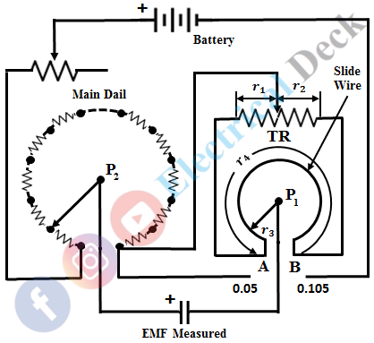
The major disadvantage with Crompton's potentiometer is that the true zero cannot be obtained, since the points P1 and P2 can never coincide. To overcome this difficulty, certain modifications have been done to Crompton's potentiometer as shown in the figure below.
In this, a shunt resistor Rsh is connected across the slide wire AB. The shunt resistor is tapped at point T. This point T is made as zero of the main dial. When the contact P1 is at a point such that, the ratios (r1 : r3) and (r2 : r4) are equal, then there is no potential difference between the zero stud and the contact P1. At this point, the slide wire has a true zero.
The slider can move towards its left giving negative readings and towards its right giving positive readings. The typical range of values of slide wire varies from -0.05 to 0.105 V.
Modern Potentiometer :
In modern DC potentiometers, a separate standard cell dial circuit is provided as shown in the figure below. By this, the speed of measurement increases. Also, convenience is obtained as it is not required to disturb the settings of potentiometer while the balance point of the standard cell is verified at any time throughout the span of measurement.
The standard cell dial circuit consists of a standard cell, standard resistor R, and dial 1. The meter is calibrated by throwing the position of Double Pole Double Throw (DPDT) switch to ab.
Now, the measurement of unknown emf Vx is carried out by throwing the DPDT switch to position a1 b1 and by adjusting the resistance of dial 2 (in steps) and dial 3 the balance is obtained. At any time during the span of measurement, the balance of standard cell can be checked by simply switching the DPDT switch to position ab without altering the measuring circuit dials.
Whereas, in the case of olden day potentiometers, where no separate dial circuit was provided for standard cell, if the operator wants to check the standard cell balance during the measurement the slide wire (which is common to both standard cell and unknown emf) position has to be adjusted. This was a time consuming process and is avoided in modem dc potentiometers.


