A potentiometer is a measuring device that can be used for measuring unknown resistance, voltage, and power in a circuit. Other than this a potentiometer application includes calibration of various measuring instruments like voltmeter, ammeter, and wattmeter.
Calibration of an instrument is nothing but checking the correctness or accuracy of the instrument. So that the error (difference between actual and measured value) introduced in the instrument while measuring can be known and actual or ideal value can be determined. In the process of calibration, the resultant or measured value is compared with the actual standard value.
Let us see how a dc potentiometer can be used for calibration of voltmeter, ammeter, and wattmeter also in measuring resistance, voltage, and power.
Calibration of Voltmeter :
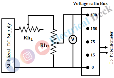
The circuit diagram for the calibration of the voltmeter is shown below. It consists of a stabilized ac supply, rheostats, voltmeter, voltage ratio box, and potentiometer. The basic and important requirement of the circuit is that the input ac supply must not have any fluctuations. Any fluctuation in the supply will have a corresponding change in the calibration of the voltmeter.
Hence, to avoid this a stabilized ac supply must be used. Two rheostats Rh1 and Rh2 are used to have a very precise control so that the voltmeter accurately coincides with the major divisions. A voltage-ratio box is used to reduce the voltage across the voltmeter and applied to the potentiometer.
The potentiometer reads the true value of the voltage. If this value is matched with the voltmeter readings, then the error is zero. However, if these two readings do not match, an error is encountered. This error may be positive or negative depending on the relative value of the voltmeter and the potentiometer. In order to have greater accuracy, the voltage should be measured near the maximum range of the potentiometer.
Calibration of Ammeter :
The connection diagram for the calibration of the ammeter is shown in the figure below. The circuit consists of a stabilized ac supply, variable resistor, ammeter, a standard resistor, and a potentiometer. The ammeter is connected in series with the standard, non-inductive resistance of known value R. The potentiometer is connected across the standard resistor.
Let VR be the potentiometer reading which corresponds to the voltage across R. Then the current through R is given by, IR = VR/R. Let I be the ammeter reading. The two values i.e., IR, I will be the same since the ammeter and standard resistor are in series. Since the value of standard resistor is accurately known, accurate calibration of ammeter can be obtained by this method.
Calibration of Wattmeter :
For calibrating the wattmeter using a potentiometer, a phantom loading arrangement is used as shown below.
In order to avoid the current and voltage values beyond the rating, ammeter and voltmeter are employed in the circuit respectively. The accurate value of current through the current coil, I is calculated by measuring the voltage drop across the standard resistor R using a potentiometer i.e., IR = VR/R.
The accurate value of voltage across pressure coil, V is calculated by measuring the output voltage of voltage-ratio box, VR using potentiometer i.e., V = KVo (where K = multiplication factor of the voltage-ratio box). So, the position indicated by wattmeter is marked as VI,
This procedure is repeated for all the values of V and I which are varied by using potential divider and rheostat respectively. For each particular setting both VR and Vo are measured by switching the DPDT switch to POS1 and POS2 respectively.
Measurement of Resistance :
The figure below shows the circuit diagram for the measurement of resistance using potentiometer. Rx is the unknown resistance connected in series with Rs, which is a known standard resistance. R1 is the variable resistor used to limit the current I through Rs which is monitored using ammeter A. The DPDT switch is used to connect the terminals of the potentiometer across Rs or across Rx.
Let, the voltage across Rx be Vx and voltage across Rs be Vs. Here, Vx = IRx, Vs = IRs and I = Vs/Rs. Substituting I in Vs, we get,
Measurement of Power :
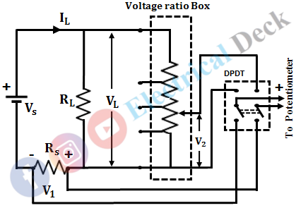
The connection diagram for measuring power using a potentiometer is shown below. Rs is a known standard resistance connected in series with the load resistance RL. A voltage-ratio box is connected across the load resistance RL. The duty of the voltage-ratio box is to step down the load voltage VL, as the potentiometer has a limited range of voltage measurement.
By measuring the voltage drop V1 across Rs, the load current can be calculated as IL = V1/Rs and by measuring the output voltage of voltage-ratio box V, the load voltage can be calculated as VL = KV2 (where K = multiplication factor of the voltage-ratio box). Therefore, the power consumed by the load resistance is given as,
Measurement of Voltage :
A general purpose potentiometer can measure voltages less than 2 volts. It cannot measure the voltages greater than 2 volts directly. Hence, in order to measure voltages of higher values, a voltage-ratio box is connected to the potentiometer.
A volt-ratio box consists of a potential divider with various tappings on the input side. Each tapping is marked with the voltage and with the corresponding multiplying factor of the potentiometer.


