In the last two articles, we have seen the determination of voltage regulation using the synchronous impedance method and MMF or ampere-turn method. The drawback of the synchronous impedance method is that the regulation obtained is always higher than the actual value. While with the ampere-turn method the regulation obtained is lower than the actual value. This can be overcome by using the method called 'Potier's Triangle Method or Zero Power factor Method (ZPF)'.
This method gives more accurate results in finding voltage regulation. In Potier's method, the drops due to armature leakage reactance and armature reaction effect are treated separately. While in synchronous impedance and MMF methods all the quantities are treated as emf and mmf quantities respectively (which are away from reality).
In order to obtain voltage regulation using potier's method. The armature leakage reactance XL (emf quantity) and armature reaction effect (mmf quantity) are determined separately by performing two tests on the alternator.
- Open circuit test
- Zero power factor test
Open Circuit Test :
The below shows the circuit diagram to perform the open-circuit test on the alternator with open-circuited armature terminals.
Let the alternator is running at synchronous speed driven by the prime mover with no-load connected across the armature. The voltmeters connected across the armature open-circuited lines measure open-circuit voltage.
- At first, adjust the prime mover speed to the synchronous speed of the alternator.
- The rheostat in the field circuit (rotor) is set to its maximum value.
- Now increase the field current by varying the field rheostat so that flux produced by field winding increases.
- The increased flux increases induced emf in the alternator thereby increasing the terminal voltage of the alternator.
- The various values of open-circuit line voltage Voc at different field current If values are noted.
- The below curve shows the open-circuit test characteristics drawn between field current and open-circuit voltage.
Zero Power Factor Test :
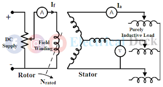
To perform a zero power factor test a purely inductive load is connected to the alternator i.e., across the armature terminals as shown below.
At first, the alternator is made to run at its synchronous speed. Now by varying the field excitation and inductance of the inductive load the machine is made to supply its full-load rated armature current. Since the load connected is purely inductive the alternator will operate at zero power factor lagging (cos 90°). Hence this method is also called as 'Zero Power Factor Method (ZPF)'.
The below shows the saturation curve of terminal voltage against field excitation (field current) required to deliver full-load short-circuit armature current.
- Point A shows the field current corresponding to zero terminal voltage.
- The line OB tangent to O.C.C. is drawn called an air-gap line.
- The point P is obtained at rated terminal voltage while the alternator delivering full-load current at ZPF lagging.
- From P, PQ is drawn equal to OA and a line QR parallel to air-gap line which intersects O.C.C. at point R.
- Now draw a line from point A parallel to PR intersecting O.C.C. at B. Thus the triangles OAB and PQR are similar.
- Draw the perpendiculars in triangles OAB and PQR from point B and R such that they meet at point C and Q on the lines OA and PQ respectively.
- The triangle PQR is called potier triangle which remains constant for a given armature current. Hence it can be transferred to other points like P'Q'R' to obtain △ OAB.
In the △ PQR the line RS represents the armature leakage reactance drop IXL. The length PS gives the field current Iar necessary to balance the armature reaction effect at full-load. Since the load is inductive the effect of armature reaction is wholly demagnetizing. Similarly, the length SQ gives the field current Ir necessary to balance armature leakage reactance drop.
Regulation Calculation :
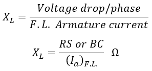
From the graph, the armature leakage reactance XL, known as potier reactance is obtained as,
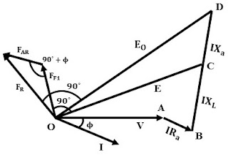
To determine the regulation phasor diagram is drawn. Taking V as a reference, I is drawn at lagging p.f. with angle Φ because the load is inductive. The armature resistance and armature reactance drop IRa and IXL is drawn parallel and perpendicular to current I from the tip of V respectively.
Phasor sum of rated voltage V, armature resistance drop IRa, and armature leakage reactance drop IXL gives induced emf E i.e., OC. The field excitation corresponding to E is obtained from O.C.C i.e, FF1 at 90° ahead as shown below.
The induced emf obtained is without the armature reaction effect. From potier triangle, PQR the field current required to balance the armature reaction effect is obtained i.e., PS, which is say FAR. The vector sum of excitations FF1 and FAR gives the total excitation FR required to overcome both the armature leakage reactance drop and armature reaction drop.
Once the total excitation (field current) is known corresponding induced emf Eo is obtained from the O.C.C. Therefore, the regulation of the alternator is determined as,


