A repulsion motor is one among single-phase commutator-type motor with a wound rotor and brushes arrangement. It works on the principle of magnetic repulsion between two poles. A repulsion motor will start with repulsion between two unlike poles and then runs as an induction motor. Let us see the construction and working principle of the repulsion motor.
Construction of Repulsion Motor :
A repulsion motor is constructed in the following manner,- The construction of the stator is similar to that of a single-phase or a split-phase induction motor. It is of non-salient pole type, wound with single-phase winding for four, six, or eight poles.
- The rotor of the repulsion motor is same as the armature of a dc machine with a commutator and brushes assembly. The rotor is also wound with distributed winding in the rotor core slots.
- The commutator can be radial or vertical with brushes attached to it. Here the brushes are movable on the commutator surface with the rotor.
- The difference in construction that makes a repulsion motor is that the brushes on the rotor are short-circuited with each other through a low resistance conductor called Jumper. There is no electrical connection to the rotor, unlike the rotor connection in a dc machine. The stator winding is connected to the single-phase ac supply and power to the rotor is given through the induction principle.
- It should be noted that, since brushes are movable, the brush axis cannot be with the stator field pole axis all the time. In the repulsion motor, the position of brush axis plays a vital role in the motor operation.
Working Principle of Repulsion Motor :
Let us see how the torque is produced and the motor is able to rotate. The repulsion motor uses both repulsion and induction principles. Let us consider a 2-pole motor of projected pole-type.
But in practice, the stator is of smooth cylindrical type without any projected poles (non-salient type). When the single ac supply is fed to the stator winding. Assume that the direction of the magnetic field is from top to bottom i.e., N to S, with a vertical magnetic axis at the center as shown below.
Since the supply is alternating, the flux produced will also be alternating in nature. This alternating flux when links with the rotor, it induces an emf in the rotor conductors by induction principle. Let us see torque developed on the rotor at different instants of the brush axis with respect to the stator field pole axis.
When brush axis is aligned with field axis (α = 0°) :
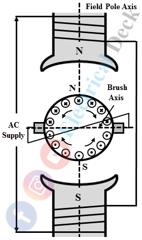
When the brushes are kept in such a way that their axis gets aligned with the field pole axis. The direction of induced emf in the rotor conductors depends upon the position of short-circuited brushes and also can be found from Lenz's law.
Since the short-circuited brushes are co-linear with the field pole axis. This causes an emf induced in upper-half conductors to flow upward, and in the lower-half conductors to flow downwards as shown below.
As a result, the upper-half rotor conductors produce N-pole and the lower-half with S-pole. This causes the upper-half conductors to experience a force in a downward direction, and lower-half conductors with upward force due to repulsion force by the two field poles at the same time. Hence, no torque is produced when the rotor poles are face to face with the stator poles.
When brush axis is perpendicular with field axis (α = 90°) :
The below shows the diagram with the brushes position that its axis is at 90° from the stator field pole axis. At this position, the direction of rotor-induced emf is similar to that of the previous case as shown below by dots (.) and cross (×).
Hence, the voltage across the two brushes becomes zero, and no current flows in it. Therefore, the net torque produced on the rotor will be zero and it remains at the same position.
When brush axis is shifted with some α° from field axis :
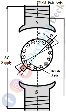
Let us consider that the brush axis is kept at a position other than the two previous cases. The below figure shows with brush axis shifted by an angle α° in a clockwise direction.
At this position, the emf induced in the rotor causes pole N at the upper right brush and pole S at the lower-left brush. This causes a repulsion force on rotor pole N by the field pole N, and on the rotor pole S by the field pole S.
Thus, the torque is developed and the rotor rotates in the clockwise direction. Suppose, if the brush axis is shifted in an anti-clockwise direction with an angle of α°. The torque will be produced in the anti-clockwise direction.
Therefore, the direction of rotor rotation depends upon the direction of the brush axis shifted. The magnitude of torque produced depends upon field flux and rotor-induced current. The flux produced by the field winding depends upon the amount of field current supplied.
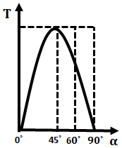
Hence, the torque developed is proportional to the square of the field current. This states that a repulsion motor develops high starting torque and it depends upon the amount of brush axis shifted from the field pole axis. From the above diagram, if α is the angle between the brush axis and field pole axis. The starting torque produced on the rotor will be,
To obtain maximum torque the angle of α should be 45°. Therefore, the repulsion motor develops maximum torque when the brush axis is adjusted at 45° from the field pole axis as shown below.
A repulsion motor exhibits excellent torque-speed characteristics. Compare to split-phase induction motors, repulsion motors develop high starting torque.


