In the last article, we have derived the equation for EMF induced in the alternator. The equation for per-phase induced emf Eph in an alternator is given as,
When an alternator is loaded the whole induced emf doesn't appear across the output terminals. As the load on the alternator is varied, its terminal voltage Vph also varies due to the following drops,
- Voltage drop IaRa due to armature resistance Ra.
- Voltage drop IaXs due to armature leakage reactance XL.
- Voltage drop due to armature reaction.
The induced emf in the alternator has to supply the above drops while supplying the load. Therefore the equation for terminal voltage of an alternator is given as,
From the above voltage equation, let us draw the phasor diagram of a synchronous generator operating at different load power factors. The relation between terminal voltage and current for power factor analysis can be done by the phasor diagram.
Let,- Eph = Induced emf on load per phase.
- Vph = Terminal voltage per phase
- Ia = Armature current
- Φ = Phase angle between Ia and Vph (i.e., p.f.)
- Ra = Armature resistance per phase
- Xs = Synchronous reactance (leakage reactance + armature reaction reactance)
Taking Vph as the refernce phasor. The phase relationship between armature induced emf E due to field flux Φf and the current flowing through the armature Ia depends upon the power factor of the load.
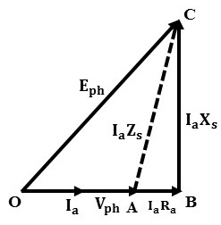
Phasor Diagram at Unity Power Factor Load :
When the alternator is driving a unity power factor load (resistive) i.e., cos Φ = 1. The armature current Ia will be in phase with Vph as shown below.
From the triangle OBC, the expression for induced emf Eph is given as,
At unity power factor cos Φ = 1 and sin Φ = 0. The equation is modified as,
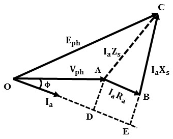
Phasor Diagram at Lagging Power Factor Load :
For lagging power factor loads the current Ia will lag the terminal voltage Vph with an angle Φ. At zero lagging power factor (pure inductive) the current Ia lags the voltage Vph exactly by 90°. The below shows the phasor diagram for the lagging power factor.
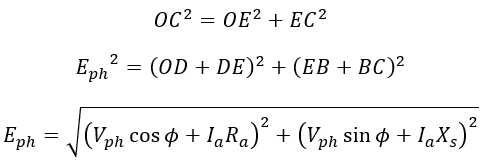
The armature resistance drop IaRa is due to armature current Ia. Hence it always lies in phase with current Ia i.e., DE. Therefore, from the triangle OCE,
Phasor Diagram at Leading Power Factor Load :
Similar to the lagging power factor the current Ia leads the voltage Vph by Φ at leading power factor loads as shown below. At zero leading power factor (pure capacitive) current Ia lead Vph exactly by 90°.


