In this article let us draw the phasor diagram of synchronous motor and also derive the expression for back emf Eb and load angle α for various factors.
Analysis of Phasor Diagram Under Normal Conditions :
Let,- V = Supply voltage per phase
- Ia = Armature current per phase
- Φ = p.f. angle or angle between V and Ia
- cos Φ = p.f. at which motor is working
- α = Load angle or Torque angle corresponding to the load on the motor
The phasor diagram with all the above details at normal excitation is shown below.
When the value of back emf is equal to applied voltage Eb = V then the synchronous motor is said to be at normal excitation. The angle θ is called an internal machine angle or impedance angle. It is constant for a motor.
The significance of θ is that it tells us that Ia lags behind Er by an angle θ. Practically armature resistance Ra is very small compared to reactance Xs and hence θ tends to 90°. It is expressed as,
From the phasor diagram, armature current is given by Ia = Er / Zs and, synchronous impedance Zs = Ra + jXs. The vector difference of Eb and V gives the resultant emf Er which represents Ia Zs. The resultant emf Er is expressed as,
The nature of the power factor is lagging if Ia lags V by angle Φ while it is leading if Ia leads V by angle Φ. Let us see the phasor diagram and expression for back emf and load angle at different power factor loads.
Phasor Diagram at Lagging PF :
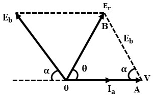
When field excitation is made in such a way that back emf is less than the applied voltage (Eb < V) then the motor is said to be 'Under-Excited'. Here the torque angle α is small and Ia lags behind V with poor power factor angle Φ. The phasor diagram is shown below.
Applying cosine rule to triangle OAB,
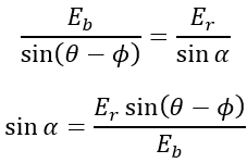
Applying sine rule to triangle OAB,
Hence load angle α can be calculated once Eb is known.
Phasor Diagram at Leading PF :
When excitation is increased in such a way that Eb > V, the motor is said to be 'Over-excited'. Here the current Ia is comparatively larger and leads the voltage V by an angle Φ as shown below.
Applying cosine rule to triangle OAB,
Applying sine rule to triangle OAB,
Hence load angle α can be calculated once Eb is known.
Phasor Diagram at Unity PF :
The change in excitation for which the armature current will be in phase with voltage so that power factor becomes unity, this occurs when E ≅ V. Therefore Φ = 0 and cos Φ = 1.


