In the last article, we have seen the phenomenon of armature reaction in a dc generator. There are various effects in the dc generator due to armature reaction.
- Due to the demagnetizing effect of armature flux on the field flux, there will be a reduction in the induced emf thereby terminal voltage of the generator drops.
- The armature reaction affects the distribution of air-gap flux and causes in shifting of the magnetic neutral axis (MNA) from GNA. Since brushes were present on GNA, if the brush axis is not shifted to MNA it affects the commutation action.
- Normally, iron losses are constant either the machine is on load or on no-load. But the armature reaction causes an effect on flux density when the generator is loaded. Thus the iron losses are more when the generator is loaded compared to no-load.
There are some arrangements made to the generator to neutralize the armature reaction effect.
Methods to Reduce Effect of Armature Reaction for Better Commutation :
By Increasing Brush-Contact Resistance :
By using high brush contact resistance with the commutator segment undergoing commutation the sparking can be eliminated. Let us see how it is achieved.
Consider a winding coil 'A' with two commutator segments and a brush in contact with segment 1. When segment 2 approaches the brush some part x of current I flow through the coil 'A' in a forward direction (rotation of armature) as shown in figure (a) below. In figure (b) when the brush is in the middle of the two segments no current flows in coil 'A'. Now the current flows in the reverse direction when segment 1 leaves the brush shown in figure (c).
While in the process segment 2 completely reaches the brush more and more current flows in coil A. So that complete reversal of current takes place in coil A by the time when brush reaches completely to segment 2 as shown in figure (d). During this complete reversal of current sparking is produced on the segment 1 surface with the brush.
So by increasing the brush-contact resistance (using carbon brushes) with segment the sparking can be reduced during the current reversal. The contact resistance is in such a way that, the commutator segment with a lower contact area (segment 1 in the above case in figure (c)) with the brush having high resistance.
Shifting of Brushes :
In the article armature reaction of dc generator. We have seen that under load conditions due to the effect of armature flux on the main flux the distribution of air-gap flux gets distorted. This causes to change in the magnetic neutral axis i.e., MNA gets shifted by a certain angle.
Since the brush axis should lie along the magnetic neutral axis, but the change in the magnetic neutral axis emf will induce in the coil undergoing commutation producing sparking at the brushes.
In order to obtain sparkless commutation, the brush axis should also move along the magnetic neutral axis. But in practice, it is difficult to know the exact shift of the magnetic neutral axis because it depends upon the magnitude of load current i.e., load on the machine. Therefore it is also difficult to maintain the brush axis along the magnetic neutral axis.
Using Compensating Winding :
There are two types of effect on the field flux due to armature flux nothing but armature reaction effect. Some of the armature conductors flux weakens the field flux called demagnetizing effect, and some of the armature conductors flux distort the field flux called the cross-magnetizing effect.
Since this effect depends upon load on the machine i.e., load current or armature current. In a large dc machine, variation in the load varies flux in the machine either forward or backward.
This causes statically induced emf in the armature coils and produces sparking at the commutator surface (as seen in the brush shifting method). This sparking can short-circuit the entire armature circuit in large dc machines that carry large armature currents.
The cross-magnetizing effect of armature reaction in large dc machines can be neutralized by using auxiliary winding called 'Compensating Winding'. Compensating windings connected in series with the armature windings are placed in embedded slots on the main poles and faces towards the armature conductors that are responsible for the cross-magnetizing effect as shown above.
The winding is made in such a way that the flux produced by the compensating windings is in opposite direction to the armature flux with an equal magnitude of mmf as that armature flux mmf. Therefore it neutralizes the armature conductors flux responsible for the cross-magnetizing effect.
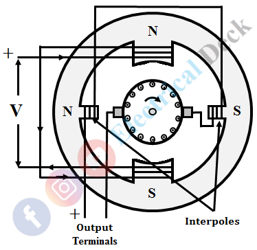
Use of Interpoles or Commutating Poles or Compoles :
These are small auxiliary poles wound with a copper conductor of few turns. They are placed in between the main poles and connected in series with the armature winding as shown below.
Similar to compensating winding, interpoles neutralize the effect of armature conductors mmf by producing a counter mmf in the interpolar region (GNA). The difference is that interpoles nullify the reactance voltage induced in the coil that makes a delay in the reversal of current in the coil undergoing commutation. While the compensating winding produces an mmf to counterbalance the mmf produced by armature conductors.


