A stepper motor is an electromechanical device that converts a train of input pulses into a train of step movements. In the recent two articles, we have seen permanent magnet and variable reluctance stepper motors.
Now let us see about another type of stepper motor called 'Hybrid Stepper Motor'. The hybrid stepper motor works on the combined principles of permanent magnet and variable reluctance stepper motor. It has both the features of a permanent magnet and variable reluctance stepper motor, hence smooth control of motion with very small steps can be achieved.
Construction of Hybrid Stepper Motor :
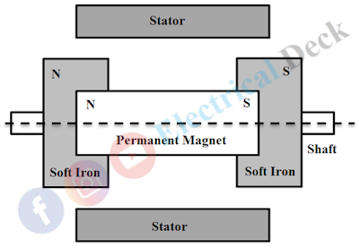
The stator construction is similar to variable reluctance or permanent magnet stepper motor. It consists of multiple laminated tooth-like projected poles with exciting coils wound on them. The rotor consists of a permanent magnet placed axially on the rotor shaft with axial pairs of poles N and S as shown below.
Two identical stacks of soft iron also called end-caps are attached to the two ends (N and S) of the axially magnetized permanent magnet. These iron stacks consist of tooth-like projections and are magnetized by the axial permanent magnet to which they are attached.
Thus iron stacks or rotor teeth on one end become the north pole while the other with a south pole. The rotor poles are displaced at a certain angle for proper alignment with the stator during rotation.
Working of Hybrid Stepper Motor :
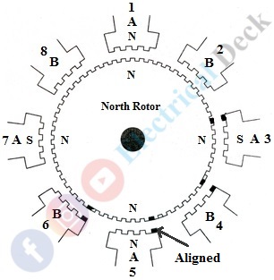
Let us consider a hybrid motor with 8 stator poles excited by their stator windings. Each stator pole consists of 2 to 6 projected teeth as shown below. The rotor is made up of composed tooth cups of a permanent magnet. The torque is produced due to the interaction of rotor flux with the stator flux and is proportional to the stator exciting current.
The stator has a two-phase construction (Phase-A and Phase-B). The winding coils are placed at 90° from one another, making up each phase. Poles 1, 3, 5, and 7 forms phase A and poles 2, 4, 6, and 8 form phase B.
Each phase is wound so that the poles 180° apart are with the same polarity, while the poles 90° apart are with opposite polarity. When the current in a phase is reversed, the axis of the poles gets changed from the north pole to the south pole or vice-versa.
When phase A is excited, the poles 1 and 5 are energized with the pole N and the poles 3 and 7 with the pole S. This makes rotor pole N align with stator pole S (i.e., 3 and 7) and rotor pole S with stator pole N (i.e., 1 and 5).
Suppose, if phase B is excited the rotor will make a step by one-quarter of a tooth pitch. The poles to be energized will depend upon the direction of rotation to be done by the rotor.


