In the last two articles, we learned about the effect of resistance and leakage reactance on the transformer. Now let us see the effect on the transformer with both resistance and leakage reactance i.e., nothing but the impedance.
Resistance and Leakage Reactance or Impedance of a Transformer :
If R1 and X1 are the resistance and leakage reactance of the primary winding. Similarly, R2 and X2 are the resistance and leakage reactance of the secondary winding as shown below.
Then the impedances Z1 and Z2 due to resistance and reactance of the primary and secondary winding is given as,
There will be voltage drops that cause power loss in the primary and secondary windings due to resistance (as copper losses) and due to leakage reactance (as magnetic leakage flux). Hence, the voltage across the primary and secondary windings is given by,
Where,- V1 & V2 = Primary applied voltage and secondary terminal voltage.
- I1 & I2 = Primary and secondary currents.
- E1 & E2 = Primary and secondary induced EMFs.
- I1 Z1 & I2 Z2 = Power loss in the primary and secondary windings.
Phasor Diagram with Different Loads :
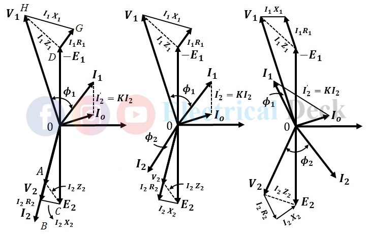
The vector or phasor diagram for the above transformer with power loss for resistive, resistive-inductive, and resistive-capacitive loads are shown in the below figures respectively.
At first draw voltage vector V2, and I2 represent secondary current in phase as well as in magnitude. Since voltage drop in the secondary winding i.e., drop due to resistance I2 R2 will be in phase with current I2, and drop due to leakage reactance I2 X2 will lead current I2 by 90⁰.
Now draw a line AB parallel to current I2 and equal to I2 R2 in magnitude and draw BC perpendicular to AB and equal to I2 X2 in magnitude such that line AC represents the total drop impedance I2 Z2. So vector represents secondary induced emf E2.
Draw no-load current Io, and I2' parallel to I2 (and equal to K I2). The sum of Io and I2' gives I1. Draw OD equal to induced emf E1. So draw DG equal to I1 R1 and parallel to I1 and I1 X1 perpendicular to DG. So vector OH represents V1 in magnitude and phase.
Equivalent Resistance and Leakage Reactance or Impedance of the Transformer :
The impedances Z1 and Z2 of the transformer on both the windings can be transferred either to the primary or secondary side and referred to as the transferred side. This shifting makes the calculations easy and simple.
Equivalent Resistance and Leakage Reactance or Impedance Referred to primary side :
The equivalent impedance referred to the primary side can be done by transferring the secondary resistance and reactance to the primary side as shown below.
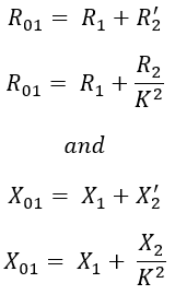
Here, the total resistance R01 (R1 + R2') referred to the primary side and total reactance X01 (X1 + X2') referred to the primary side is given by, Therefore, the total impedance Z01 which is the algebraic sum of both resistance and leakage reactance referred to the primary side is,
Equivalent Resistance and Leakage Reactance or Impedance Referred to secondary side :
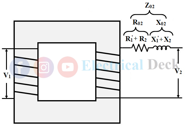
Similarly, the equivalent impedance referred to as the secondary side can be done by transferring the primary resistance and reactance to the secondary side as shown below.


