In the no-load test of a transformer, the secondary winding of the transformer is kept open without connecting any load. The primary side of the transformer is connected to the ac supply and evaluates the behavior of the transformer under the no-load condition.
In the last article, we have discussed an ideal transformer i.e., a transformer without losses or wastage (i.e., no iron loss and copper loss). But, in practice, when a transformer is loaded, there will be an iron loss in the core and copper loss in the primary and secondary windings.
Also when the transformer is on no-load, the primary current is not completely reactive. Since the core is subjected to alternating flux the primary current has to supply,
- Iron losses in the core i.e., hysteresis and eddy current loss, and
- There will be a small amount of copper in the primary winding only (since no current in the secondary).
No-load Operation of Transformer :
Under the no-load condition, when the supply V1 is given the primary winding the no-load current Io flows through the primary winding. This alternating current will set up an alternating flux Φ in the core. Since there is no connection to the secondary no current flows through it as shown below.
The alternating flux produced links with the secondary winding and will induce emf in both the windings. The amount of induced EMFs E1 and E2 depends upon the number of turns in the primary and secondary windings. The induced emf due to the linking of flux will lag the flux by 90°.
However, the primary no-load current is to supply eddy-current loss and hysteresis loss in the core and a small amount of copper loss (I2 R) in the primary winding.
Thus the no-load Io is divided into two components,- The component of current responsible for producing the flux in the core is called a Magnetizing Component of current Im. It is a purely reactive component also called the wattless component.
- The component of current Ic which supplies iron losses and a small amount of primary copper loss is called the Working or Active Component. It is also called the watt-full component of Io.
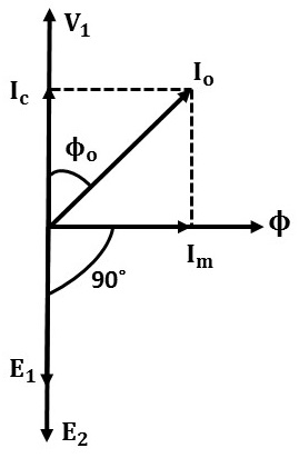
Phasor Diagram of Transformer on No-load :
- There will be a 180° (opposite) phase difference between the primary voltage V1 and primary induced emf E1. The magnitude of induced emf will be approximately equal to the magnitude of the supply voltage.
- As seen above the no-load current Io has two components i.e., it is the vector sum of current Im and Ic. Since the winding is of an inductor coil, in a loss-less inductor coil the current lags the voltage by 90°. Hence the magnetizing current Im lags the supply voltage by 90°.
- However, the core loss component Ic is in phase with the voltage V1 such that V1 Ic = core loss.
- The magnetizing component Im set up the flux Φ which is common for both primary and secondary windings. Hence it is taken as the reference axis.
- The alternating flux Φ induces emf E1 and E2 in the primary and secondary windings respectively which lags the flux by 90°.

From the phasor diagram,- Wo = No-load power input
- V1 = Primary supply voltage
- E1 & E2 = Primary and secondary induced emf's
- Io = No-load primary input current
- Ic = Working or active or iron loss component of Io
- Im = Magnetising or watt-less component of Io
- cos Φo = Primary power factor on on-load.
Therefore, no-load power input (= Iron loss) is,
Here Io has two components,- Working or active component Ic = Io cos Φo
- Magnetizing component Im = Io sin Φo.
Obviously, Io is the vector sum of Ic and Im. Hence,
The following points should be noted :
- Normally, the no-load current Io is very small as compared to the full-load primary current.
- Since Io is very small, the primary no-load current that causes copper loss is also very small and can be neglected. Hence, the no-load input power Wo be equal to the iron losses of the transformer.
- Therefore, Io is also known as the hysteresis angle of advance.


