The synchronous impedance method or EMF method is one of the methods of finding voltage regulation of alternator or synchronous generator. In order to calculate regulation by this method, it requires the following data,
- The per-phase armature resistance Ra,
- The open-circuit test data shows the relationship of the characteristics between open-circuit voltage and field current, and
- The short-circuit characteristic is the graph of short-circuit current against field current.
DC Resistance Test :
The per-phase armature resistance can be calculated by performing a dc resistance test. To measure the dc resistance armature-voltmeter method is used. The calculated dc resistance value is low when compared to ac resistance. So that the obtained dc resistance is multiplied by a factor of 1.3 to obtain ac resistance. The below shows the circuit diagram for the dc resistance test.
Open-Circuit Test :
The circuit diagram for the open-circuit test is shown below. Let the alternator is running at synchronous speed driven by the prime mover with no-load connected across the armature. The voltmeters connected across the armature open-circuited lines measure open-circuit voltage.
- At first, adjust the prime mover speed to the synchronous speed of the alternator.
- The rheostat in the field circuit (rotor) is set to its maximum value.
- Now increase the field current by varying the field rheostat so that flux produced by field winding increases.
- The increased flux increases induced emf in the alternator thereby increasing the terminal voltage of the alternator.
- The various values of open-circuit line voltage Voc at different field current If values are noted
- The below curve shows the open-circuit test characteristics drawn between field current and open-circuit voltage.
The observation table for the open-circuit test is shown below.
| S.No. | Field current Ia (amp) | Open-circuit line Voltage Voc (volt) |
|---|
| Readings oberved from the test |
Short-Circuit Test :
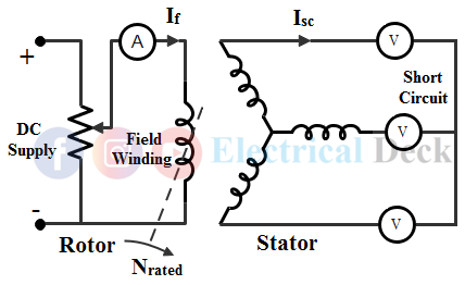
A short-circuit test is performed by running the alternator at rated speed. The below shows the circuit diagram with short-circuited armature terminals. The ammeters connected in the armature circuit measures short-circuit current.
- Before short-circuiting the armature terminals, the field current is reduced to a minimum value by increasing the resistance of the field rheostat.
- Now, the field current is gradually increased till the armature winding reads full load current.
- The full load current is obtained through armature ammeter reading.
- The various short-circuit current Isc values at a various field current Ia values are noted.
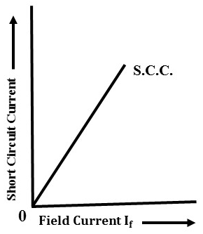
- The relation between both values gives short-circuit characteristics of an alternator as shown below.
The observation table for the short-circuit test is shown below.
| S.No. | Field current Ia (amp) | Short-circuit armature current Isc (amp) |
|---|
| Readings oberved from the test |
Calculation of Synchronous Impedance from O.C.C. and S.C.C. :
At a particular value of field current If from open-circuit and short-circuit test the ratio of open-circuit voltage to the short-circuit current gives the synchronous impedance Zs. Now at a field current If, the armature open-circuit voltage is Eoc when the winding is short-circuited, the terminal voltage is zero.
Hence, the short-circuit current Isc against synchronous impedance Zs is circulated in the armature circuit by using whole the voltage Eoc. That is,
From the above, the synchronous reactance is given by,
The below figure shows the O.C.C. and S.C.C. characteristics.
Referring to the above figure, at a field current value say OA, the alternator terminal voltage or induced emf will be AB. From the short-circuit curve with the same field current the short-circuit current in the armature windings will be AC. Therefore, from the above O.C.C. and S.C.C. curves, the synchronous impedance Zs will be,
Regulation Calculation :
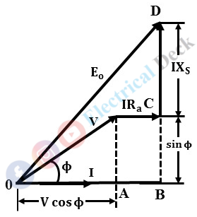
By determining the values of per-phase armature resistance Ra and synchronous reactance Xs, the vector diagram can be drawn for any load and any power factor as shown below.
From the vector diagram with a lagging power factor.
In general, Eo is given by,
Where,- Vph = Rated phase voltage
- Ia = Phase value of current depending upon the load condition.
- cos Φ = Power factor of the load
- Positive (+) sign for lagging power factor
- Negative (-) sign for leading power factor
Therefore the formula for % regulation is given as,
Note :
From various methods of determining regulation, this one yields results most likely to be inexact. The obtained value of voltage regulation by synchronous impedance method is always greater than the actual value, and therefore it is called the 'Pessimistic Method'.
Due to the effect of given armature ampere-turns on saturation. The synchronous impedance Zs varies with vary in saturation i.e., at low saturation the value of Zs will be large and vice-versa. Now, when determining the voltage regulation, Zs obtained will be higher compared actual value at working conditions. Because the value of Zs obtained is under short-circuit conditions, where saturation is very low.


