Hopkinson's test of dc machine is also known as a Regenerative Test. This test is also one of the efficient ways of determining the losses and efficiency of a dc machine. The test is performed by mechanical coupling of two identical dc machines.
In which one machine works as a generator and the other as a motor. So that the motor drives the generator by shaft coupling, while the generator drives the motor with its electrical output. Since there exists back-to-back driving operation of motor and generator, this test is also called as Back-to-Back Test.
Performance and Circuit Diagram of Hopkinson's Test :
The circuit diagram with two identical dc shunt machines whose shafts are mechanically coupled is shown below. In this test one machine is made to run as a motor and another as a generator which is connected electrically in parallel through a switch S.
In practice, the amount of electrical energy supplied by the generator is not enough to run the motor, because of the drop due to the presence of losses. In order to compensate for these losses, an external dc supply is connected to the motor. So that power drawn by the external supply is only for accounting losses in the machines.
Since the output of one machine is given to the other and vice-versa the outputs are not wasted and the test is carried at full load. Initially, the switch S is kept open and the supply is given to machine M which acts as a motor.
The speed of the motor is adjusted to its rated value by adjusting the shunt field resistance with the help of a rheostat connected to the field circuit. Thus motor runs another machine G which acts as a generator.
Now the generator voltage is adjusted by the rheostat connected to the generator field circuit until the voltmeter V connected across the switch S reads zero. This indicates that the magnitude and polarity of the generator voltage are the same as the supply. As the voltmeter reads zero the switch is closed. Therefore, by varying the excitation current of the fields with rheostats the machines can be put into at any desired load.
Calculation of Efficiency by Hopkinson’s Test :
Let,- V = Supply voltage
- I1 = Supply current
- I2 = current supplied by the generator
- I3 = Generator shunt field current
- I4 = Motor shunt field current
- Ra = Armature resistance of generator and motor
- η = Efficiency of both generator and motor
Here, we can see that input to the motor is the sum of generator output and external power supply taken on the account of losses. Similarly, the input to the generator is the mechanical output of the motor.
If V is the supply voltage the generator output power = V I2 ...(1)- Input power to the motor = V (I1 + I2)
- Output power of the motor = η × V (I1 + I2)
- Input power of the generator (output of motor) = η × V (I1 + I2)
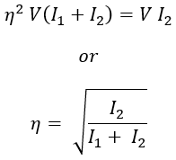
- Output power of generator = η × generator input = η × η V (I1 + I2) = η2 × V (I1 + I2) ...(2)
Therefore, from equations (1) and (2),
The derived efficiency equation is when the losses of both generator and motor are to be the same. In practice, the copper loss of the motor armature is more because the armature current is more than that of a generator. Also, the excitation current of the generator is more than that of a motor, this increases the shunt field copper loss and iron loss of the generator.
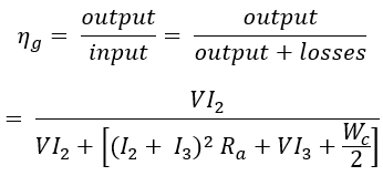
These differences in losses make the efficiency of the two machines different. If the constant losses (iron, friction, and windage losses) are assumed to be equal for both the machines. Then the constant losses are equally divided between the two machines.
We knew that total losses in both machines are equal to the external power drawn by the machines i.e., V I1. Therefore the constant losses Wc are obtained by subtracting the armature and shunt field copper losses of both motor and generator from the external power drawn.


