It is seen that emf induced in the armature conductors of a dc generator is alternating in nature. The frequency of the induced emf alternates with a frequency corresponding to the product of the speed and the number of pairs of poles.
In order to obtain direct current (unidirectional current), a commutator, and brushes are used. The commutator rotates with the armature and converts generated alternating current into direct current which is collected by the brushes and given to the load.
Similarly, in the dc motor commutator converts input direct current into alternating and given to the armature thus producing torque in the motor. Here, to run a dc machine either in the case of motor or generator it is essential to have current to be alternating which is done through process commutation by the commutator. Therefore commutator plays a virtual role in dc machines.
Action of Commutation :
Since the commutator is with the armature on the shaft it rotates continuously with the armature on the shaft. For the transformation of current from commutator to output terminals (in case of dc generator) and input terminals to a commutator (in case of dc motor) brushes are used. These brushes maintain continuous contact with the rotating commutator segments.
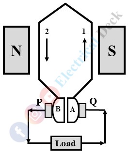
Let us consider a single-turn generator with conductors 1 and 2 connected to the commutator segments A and B with brushes P and Q. Now the direction of flow of current is that segment A with conductor 1 under the north pole is positive and segment B with conductor 2 under the south pole will be negative. The direction of current to the load is from brush P to Q as shown above.
After completing a half-cycle the conductors and segments change their position i.e., segments B becomes positive and A with negative as shown in the above figure. Here we can notice that through the direction of current changes in the conductors the commutator segments make unidirectional current to the load i.e., from brush P to Q only.
Practical Commutation :
We have seen that current in the armature conductors in one direction when under the influence of one pole. The reversal of current takes place in the conductor when it is under the influence of another pole. This reversal of current takes place along the magnetic neutral axis (M.N.A.) which would be a short interval of time.
The process in which reversal of current from one direction to another during the period when a coil is short-circuited by a brush without any sparking is called 'Commutation'. The short-circuited period of the coil with the brush is very short order of 0.0005 to 0.002 sec, it is termed as 'Commutation Period'.
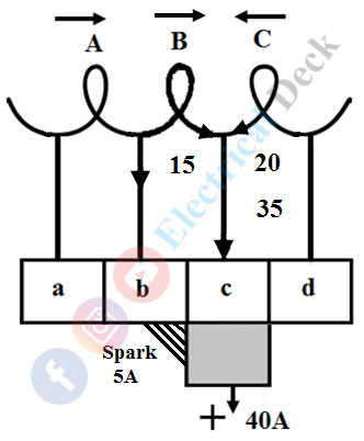
For the study of commutation, let us consider that the machine has a ring winding, a part of which is shown concentrate on coil B.- In the figure below the coil, B is about to short-circuit because the brush is about to come in touch with segment 'c'. It is assumed that each coil of armature carries a current of 20A, hence the output current at the brush is 40A.
- In the figure below the coil, B has entered its period of short-circuiting and is approximately at one-fourth of this period. The current through coil B has reduced from 20A to 10A (from right to left). Segment 'b' carries 30A and segment 'c' 10A, the total being 40A at the brush.
- In the figure below the coil, B is in the middle of the short-circuit period. The current through coil B will be reduced to zero. The two coils A and C supply a current of 20A each through segments 'b' and 'c' respectively.
- In the figure below one-fourth of the brush is under segment 'b', (which is decreasing). Coil B carries 10A in the reverse direction which combines with 20A supplied by coil C to make 30A that passes through segment 'c' to the brush. The other 10A supplied by coil A passes through segment 'b', thus a total of 40A at the brush.
- In the figure below the coil, B is at the end of the short-circuit period. The current through B should be 20A, but it is carrying 15A only. The difference current 5A jumps from segment 'b' to the brush through air thus producing a spark.
Since the armature is built with a material of high magnetic permeability. Due to which the coil possesses some amount of self-inductance. While the reversal of current in the coil due to self-inductance there will be a production of self-induced emf that retards the quick reversal. This self-induced emf is nothing but the reactance voltage.
Expression for Reactance Voltage :
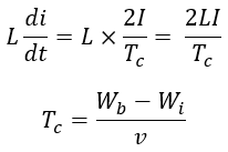
The reactance voltage is the product of the coefficient of self-inductance L and the rate of change of current. If Tc is the time required for commutation and the total change in current during the process of commutation is 2I. Then the reactance voltage or induced emf is given by,
Where,- Wb = brush width
- Wi = Width of commutator insulation
- v = Velocity of the commutator segment
If the current reversal (from I to 0 and to -I) is completed within the short-circuit time or commutation period then it known as ideal or linear commutation. But due to reactance voltage present in the coil, there will be retard or delay in the commutation said to be as 'Retarded or Under Commutation'. If the current reversal is faster than the ideal commutation then it said to be as 'Over Commutation'.
It should to noted that in both under and over commutation due to the difference in the current reversal period and commutation period sparking is produced between the brush and the commutator.
The sparking will heat the brushes and commutator and leads to a short-circuit. The different methods of improving commutation for making a current reversal in the short-circuited coil as sparkless as possible will be discussed in the next article.


