In transmission and distribution systems there can be voltage fluctuations (i.e., increase or decrease in voltage levels) when the load on the system varies. These fluctuations can also be caused due to a voltage drop in the distribution system. Sometimes these variations in voltage levels can result in quite unsatisfactory performance.
In order to maintain a constant voltage or to maintain within the prescribed limits transformer tap-changing is used. In tap-changing, the tappings on the coils of the transformer are placed so that by varying the turn-ratio voltage induced can be varied.
This arrangement is done externally to the transformer by taking coil terminals out of the transformer tank. Usually, the maximum allowable variation of the turn ratio can be up to ±2% to 5%. There are two types of tap-changing transformers,
- Off-Load Tap-Changing Transformer.
- On-Load Tap-Changing Transformer.
Off-Load Tap-Changing Transformer :
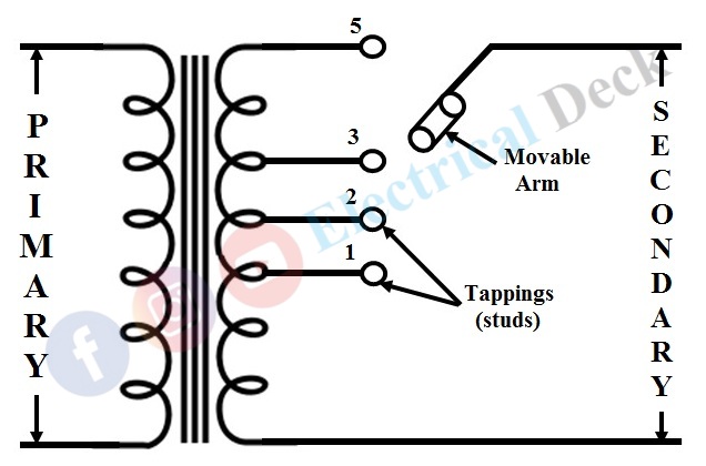
The below figure shows the off-load tap-changing transformer provided with tappings (1 to 5) on the secondary winding. The position of the movable arm on the first stud will give minimum secondary voltage and on the fifth stud will give maximum voltage across secondary.
During the light load period, the movable arm is placed on the first stud and with an increase in load, the movable arm is taken to a stud (2, 3, 4, or 5) giving a higher turns-ratio so that voltage drop in the line is compensated and the output secondary voltage is maintained.
The disadvantage of this scheme is whenever the tapping is to change load must be disconnected first from the transformer thus it is referred to as off-load tap-changing. This type of tap-changing cannot be used where continuity of the supply to the load is the main priority and it is limited where there will be a need for only slight changes in the turn ratio.
On-Load Tap-Changing Transformer :
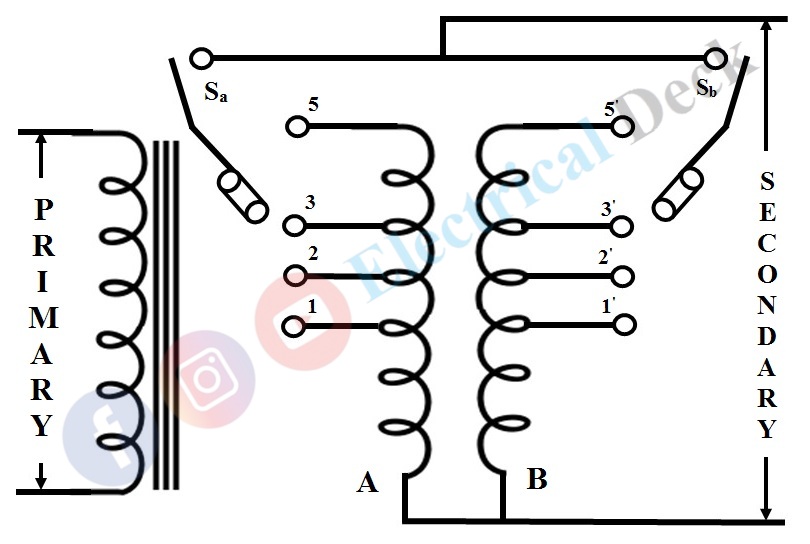
The drawback of off-load tap-changing can be overcome by using a special arrangement of coil connections to the transformer known as the on-load tap-changing of the transformer. The transformer connection for on-load tap-changing is shown below.
Here, the coils of the winding in which tappings are to be done are divided into two parallel sections with equal tapping on both sections of the coil. This forms the two winding A & B as shown above.
Under normal operating conditions both the switches (Sa & Sb) are in the closed (short-circuit) condition with identical tappings (i.e., 1 & 1'). As the winding is divided into parallel sections the total current will be the sum of the currents in winding A and B.
When the tappings are to be changed, to maintain the continuity of the supply the tap-changing process is made in such a way that,- At first, any one of the winding (either A or B) from the parallel section is to be disconnected by opening the respective switch.
- Now, the tap-changing is to be done to the disconnected winding.
- At this instant, the full-load current will pass through the connected winding (i.e., double its rated current).
- After changing the tapping to the disconnected winding is reconnected by closing the switch.
- At this moment there will be an unequal share of the load on both windings due to their different turn ratios.
- Now the other winding is disconnected and tapping is to be changed (which is equal to the tapping of previously disconnected winding).
- So that there will be an equal amount of load share on both the windings (A & B).
In this way, the continuity of the supply is maintained and more turn-ratio of tap-changing can possibly compare to off-load tap-changing of the transformer. Care must be taken to prevent the short-circuit with the windings while the tap-changing process.


