In the last article, we have seen the behavior of the transformer in the no-load condition. Let us check out the operation of the transformer, and how the transformer behaves when the load is connected across it.
Operation of the Transformer on Load Condition :
When the transformer is loaded i.e., its secondary is connected to the load terminals. The connected load can be resistive, inductive, and capacitive. At this condition, the secondary current I2 starts flowing in the secondary winding.
The phase angle of this secondary current I2 with respect to the secondary voltage V2 will depend upon the nature of the load. The current I2 will be in-phase with the secondary voltage V2 if the load is purely resistive, it lags behind the voltage if the load is inductive, and it leads the voltage if it is capacitive.
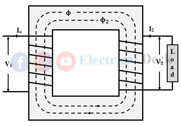
- Now, this current I2 circulates and produces its own flux Φ2, and it is in opposition to the primary winding flux Φ which is due to Io. This opposition causes to weakens the Φ and hence the resultant flux in the transformer reduces which in turn reduces the primary induced EMF E1 as shown in the below figure.
- At a moment when E1 goes on decreasing, the voltage V1 gains the upper hand over E1. This causes the primary winding to draw additional current I2' in order to restore the primary flux Φ so that E1 = V1. This additional current I2' produces additional flux Φ2' in the primary as shown below.
- The nature of the Φ2' is in such a way that it cancels out the flux Φ2 produced by the secondary current I2, but it is in the same direction as the main flux Φ. This completely causes to neutralize the magnetic effect of the secondary current. This whole process starts at the instant when the transformer is loaded. Therefore, the net flux in the transformer when it is loaded is only due to primary (i.e., φ) which is the same as that of the no-load condition shown in the below figure.
Therefore, we can conclude that whatever will be the condition of the transformer (either no-load or on-load). The operation will be the same if the voltage drop across the windings is not assumed and the core losses will remain constant under all conditions.
Hence, when the transformer is loaded, the primary has two components currents in it i.e., no-load Io and load component of primary current I2'. The total primary current is the vector sum of Io and I2' as given by,
Phasor Diagram of Transformer on Load Condition :
The phasor or vector diagrams for a transformer on resistive, inductive, and capacitive loads are drawn by taking flux Φ as the reference. Let,- V1 = Primary supply voltage.
- E1 & E2 = Primary and secondary induced emf's.
- Io = No-load primary input current.
- I2 = Primary current.
- I2 = Secondary current.
- I2' = Balancing current or load component of the primary current.
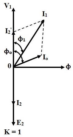
For Resistive (non-inductive) Load :
When the transformer secondary is connected to a resistive load, the current will be in phase with the voltage.
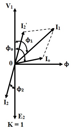
For Inductive Load :
When the transformer secondary is connected to an inductive load, the current flowing will lags with respect to the voltage as shown below.
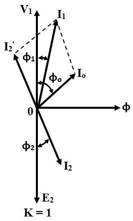
For Capacitive Load :
Similarly, when the transformer secondary is connected to a capacitive load, the current flowing will leads to the respective voltage as shown below.
In a transformer when it is loaded as compared to current I2', Io is very small, and if we neglect it. Then primary current I1 is equal to I2' (I1 = I2'). We get,


