Basically, an equivalent circuit is representing all the parameters of the transformer in a form of a circuit or diagrammatical manner. The equivalent circuit of the transformer can be used to understand the behavior of the transformer under various conditions.
Calculation of various parameters of the transformer like resistance, reactance, and impedance on the primary and secondary side can be done easily which in turn also used for determining the regulation, efficiency, and losses of the transformer.
Equivalent Circuit of a Transformer :
Consider a transformer with V1 and I2 are the primary voltage and current. Similarly, V1 and I2 are the secondary voltage and current. Let, E1 and E2 are the EMFs induced in primary and secondary windings respectively as shown below.
For the above transformer, the equivalent circuit with having transformation ratio K is shown below.
In the above circuit diagram, the primary current of the transformer serves two components Io and I2. The no-load current Io, also known as the magnetizing current also produces flux and magnetizes the core with losses in the core.
- The core losses (hysteresis loss and eddy-current loss) are represented by a non-inductive resistance Ro taking working component Iw. The current Iw, component current of Io flow through the resistance Ro such that,
- The emf E1 is induced in the primary winding due to flux produced by the magnetizing current Iμ. The magnitude of emf E1 will be less and in opposition to the applied voltage V1. The reactance Xo due to flux Φ, which is connected in parallel to the resistance Ro is such that,
Here, R1 X1 and R2 X2 are the drops due to primary and secondary winding resistance and leakage reactance respectively. The current I2 is the counter-balance current I2 of secondary on the primary. Now, we can further simplify the equivalent circuit either by shifting the primary parameters to the secondary side or vice-versa, this reduces the complexity of the circuit and computation. This can be done by using the transformation ratio of the transformer.
Equivalent Circuit of Transformer Referred to Primary Side :
The above equivalent circuit of the transformer can be modified by transferring the voltage, current, and impedance of the secondary side to the primary side as shown below figure.
By transferring all the parameters of the secondary side to the primary side with transformation ratio K. Then,- The primary equivalent of the secondary emf,
- The primary equivalent of secondary terminal voltage,
- The primary equivalent of the secondary current,
- Similarly, the secondary resistance, reactance, and impedance referred to as primary is given as,
The equivalent circuit can further be modified by transferring Ro and Xo (exciting circuit) towards the left end known as the approximate equivalent circuit as shown in the figure below. The error introduced by doing so is small and can be neglected. It should be noted that in this case Ro = V1/Iw and Xo = Vo/Iμ.
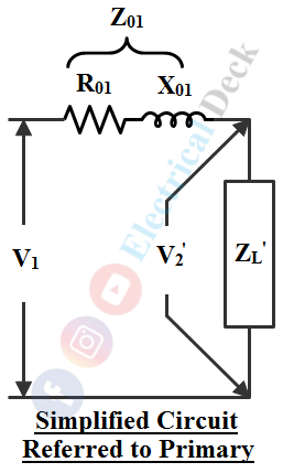
Since no-load current Io is very small, the circuit can be further simplified by neglecting Io taking as I1' = I1 shown in the below figure. Here, R01 (R1 + R2') and X01 (X1 + X2') are the total equivalent resistance and reactance of the transformer referred to as primary.
Equivalent Circuit of Transformer Referred to Secondary Side :
Similarly, how the transformer equivalent circuit is referred to the primary side, we can also refer primary side parameters towards the secondary side by transferring the primary side to the secondary side as shown below.
By transferring all the parameters of the primary side to the secondary side with transformation ratio K. Then,- The secondary equivalent of the primary emf,
- The secondary equivalent of primary voltage,
- The secondary equivalent of the primary current,
- Similarly, the primary resistance, reactance, and impedance referred to as secondary is given as,
Similarly, by neglecting the no-load current Io the simplified equivalent circuit referred to secondary side is shown below. Here, R02 (R1' + R2) and X02 (X1' + X2) are the total equivalent resistance and reactance of the transformer referred to as secondary.


