An induction motor is an asynchronous motor i.e., its speed change with a change in load. It always runs on a lagging power factor. The principle of working of an induction motor to similar to the transformer i.e., electromagnetic induction.
The equivalent circuit of an induction motor is similar to a transformer equivalent circuit because the energy is transferred from stator to rotor is essential as a transformer operation from primary to the secondary winding.
An equivalent circuit enables the performance characteristics of the induction motor. The data obtained from the equivalent circuit can be used to calculate efficiency, torque, losses, rotor output, etc. All per phase quantities are used in representing the equivalent circuit.
Equivalent Circuit of induction Motor :
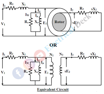
The various parameters used for developing the equivalent circuit of an induction motor are,- R1 & X1 : Stator winding resistance and leakage reactance.
- R2 & X2 : Rotor winding resistance and leakage reactance at standstill (i.e., s = 1).
- sX2 : Rotor leakage reactance at slip s (under running condition).
- Ro : No-load branch resistance and it carries working component (Iw) of no-load current Io account for the losses on no-load.
- Xo : No-load branch reactance and it carries magnetizing component (Iµ) of no-load to produce the flux.
- E1 and sE2 : Stator induced emf and rotor induced emf at slip s.
From the above parameters, the equivalent circuit of an induction motor can be drawn as shown below,
let us consider the actual rotor circuit of the motor.
From the above diagram, the rotor current I2 is given by, Here we know that the rotor input, P2 is the sum of rotor copper losses Pc and mechanical power developed Pm. Thus it is possible to represent the electrical equivalent of mechanical power developed as follows, To show the equivalent mechanical load (mechanical power conversion) in the rotor circuit. The motor equivalent circuit can be modified as,
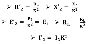
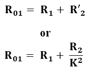
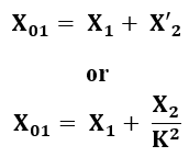
Now transfer the rotor side parameters to the stator side. While shifting the rotor side parameters towards the stator side we have to divide it by the value "K" (Where K = Ratio of the effective rotor to stator turns per phase) except the rotor current where it is multiplied by "K". When the rotor parameters are shifted they can be represented as,


