What is an Autotransformer?
An autotransformer is a special type of transformer because its construction is different from a normal transformer. It is a transformer where the secondary winding is also part of the primary winding. i.e., It is a single winding transformer where the winding is common for both the primary and secondary sides.
Its operating principle and general construction are the same as that of a conventional two-winding transformer. Economically this type of transformer is very cheaper compared to a normal transformer. Let us see the construction and operation of the autotransformer.
Construction & Working of Autotransformer :
The construction and working principle of an autotransformer are similar to a normal two-winding transformer. But, here only one winding is wound with the laminated core as shown in the below figure. The secondary winding of the transformer is taken from the portion of the primary winding. The amount of the portion connected to the secondary winding depends upon the voltage rating.
By interchanging the winding connection (making secondary as primary and vice-versa) we can make an autotransformer either as a step-up autotransformer or step-down autotransformer.
For a step-down autotransformer (V1 > V2), the connection is made in such a way that the entire winding act as the primary winding, and the secondary winding will be part of the primary winding (but not equal to primary winding) i.e., N1 > N2.
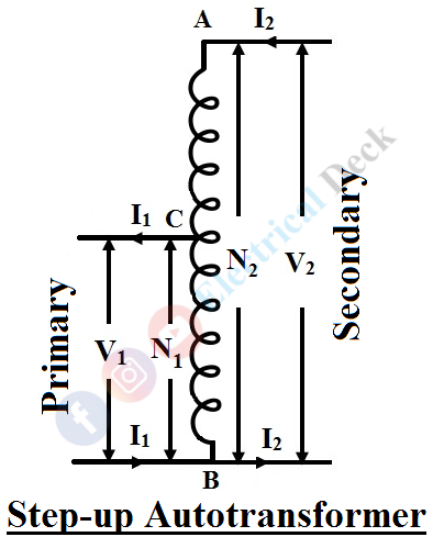
For a step-up autotransformer (V1 < V2), here the whole winding will be made as to the secondary side and the primary side will be part of the secondary side (but not equal to the secondary side) as shown below, i.e., N1 < N2.
The main use of autotransformer is due to its reduced size by making a single winding as the primary and secondary side. Which in turn reduces the amount of copper used.
Copper Saving in Autotransformer :
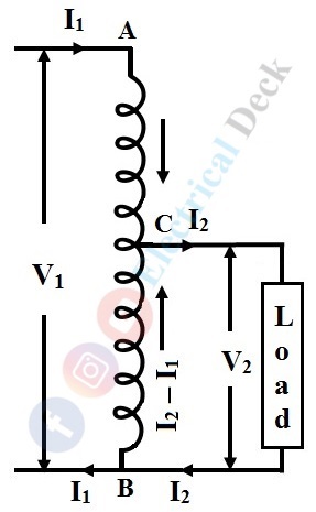
Let us consider AB as a primary winding having N1 turns and BC as a secondary winding having N2 turns as shown in the above figure. Then the transformation ratio K, of the transformer will be,
Now, by neglecting iron losses and no-load current. The current in section CB is a vector difference between I2 and I1. But in practice, the two currents I2 will be in phase opposition. Therefore, the resultant is (I2 - I1) where I2 is greater than I1.
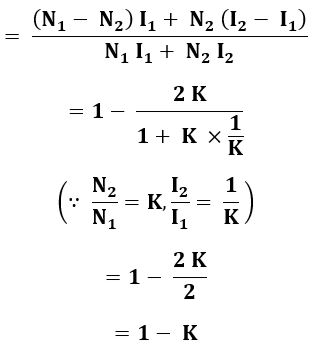
In a transformer, the weight of the copper conductor used will depend upon its cross-section area and the total length of the conductor. Therefore, as the length of the conductor (winding) increases the number of turns around the core increases, and as the cross-section of the conductor increases the current carrying capacity of the conductor increases. Hence the weight of the conductor is proportional to the product of current and the number of turns in a transformer.


