Working Principle of DC Generator :
A simple coil of wire ABCD is mounted on a shaft between two magnetic poles. The two ends of the coil are connected to two slip rings, S1, S2 which are mounted on the same shaft. The slip rings are insulated from each other from the shaft, these slip rings rotate along with the coil.
The stationary brushes b1, b2 be make proper contact with rotating slip rings and lead the current induced in the coil to the external load resistance R. This arrangement constitutes a simple loop generator.
Let us assume that the coil starts from the position and rotates at a uniform velocity in a counter-clockwise direction. In its initial position the conductor's AB and CD are moving parallel to the magnetic lines of force hence, induced e.m.f. is zero.
As the coil rotates further (o° to 90°), however, the conductors begin to cut the magnetic lines of force and therefore, the e.m.f. induces in the conductors according to the Faradays Law's of Electromagnetic Induction.
The value of induced e.m.f. depends upon the lengths of the conductor, the magnetic field strength, and the speed at which the coil rotates. The conductor has a maximum e.m.f. induced at 90°position, because the conductor moving at right angles to the flux.
In the next quarter revolution i.e. from 90° to 180°, the induced e.m.f. varies from maximum to zero gradually. During this half revolution, The flow of current is along BAMLDCB. i.e., the current through R is from M to L.
In the next half revolution i.e. from 180° to 360°, the variations in the magnitude of e.m.f. are similar to those in the first half revolution, except the direction of the current path is reversed i.e. current flow along CDLMABC and current through R is from L to M.
It is understood that the current through external load R reverses its direction after every half revolution. It also must be understood that the current not only reverse its direction but also changes its magnitude at every instant, and the current is known as alternating (ac) current. The corresponding voltage is known as dynamically induced e.m.f.
For making the flow of current unidirectional in the external load circuit, the slip-rings are replaced by split-ring. The split-rings are made of a conducting cylinder, which is cut into two halves or segments insulated from each other and the shaft with (a thin mica sheet) insulating material. The two ends of the coil are connected to these segments (s1, s2) and the brushes (b1, b2) placed over these segments.
In the first half revolution of the coil the current flows along BAMLDCB i.e. the brush b1, is in contact with segment S1, acts as the +ve terminal of the supply, and brush b2 is in contact with segment S2 and acts as a -ve terminal. In the next half revolution, the direction of the induced current in the coil will be reversed.
But at the same time, the position of segments S1 and S2 have also reversed, with the result that brush b2 comes in contact with segment S2 which is now +ve and the brush b2 is in contact with segment S1 which is now -ve. Thus the current in the external load R again flows from M to L. This current is unidirectional.
The position of the brushes is so arranged that the change of segments from one brush to another takes place when the plane of the rotating coil is at right angles to the plane of the lines of flux since in this position the induced e.m.f. in the coil will be zero.
It should be noted that the current induced in the coil sides is alternating, but it becomes unidirectional in the external load due to the rectifying action of the split ring known as a commutator.
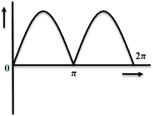
A pulsating direct current such as given by a single coil generator is not suitable for most commercial purposes. However by employing a large number of coils and commutator segments, with the coils evenly distributed around the surface of the armature the voltage can be increased and may be kept constant.
Conversion from AC to DC by Commutator :
The commutator is one of the major rotating parts of a dc Generator. It is mounted on the same shaft side by the armature. Armature winding is connected to commutator lugs.
Usually, the negative half-wave of AC generated in armature winding is converted to positive half by the commutator (or split-ring). The alternating current induced in armature conductors is made unidirectional in the external load due to rectifying or conversion action of split-ring or commutator.
Working of DC Generator :
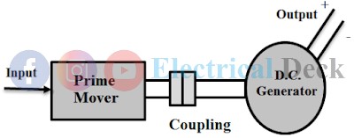
As explained before the d.c generator converts mechanical energy into electrical (DC) energy. The generator is usually coupled to a prime-mover. The prime mover may be a diesel/petrol engine, or a turbine depending upon the rating and application of the generator.
The prime mover converts some sort of energy (diesel/petrol/water/steam/gas etc) into mechanical energy. Thus mechanical energy is supplied to the generator (i.e., generator input).
If the generator is very small for commercial purposes i.e. for a shop or small workshop or cinema etc. The prime mover is a diesel engine. If the generator is very big like in power stations then the prime mover will be a turbine. Again depending upon the resources the turbine may be a water turbine, steam turbine, gas turbine, etc.
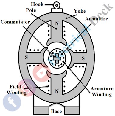
When the prime-mover output is given to the generator, the generator armature starts rotating. Usually, the poles on the yoke are made of permanent magnets. Therefore, the armature conductors cut the weak magnetic field established by permanent magnets and a small amount of e.m.f. is induced in the armature winding according to Faraday Laws of Electromagnetic Induction.
This induced e.m.f circulates a small amount of current through the field winding and strengthens the magnetic flux established and hence the induced e.m.f. Thus due to the reinforcement of the flux and e.m.f. the generator establishes the rated voltage.


